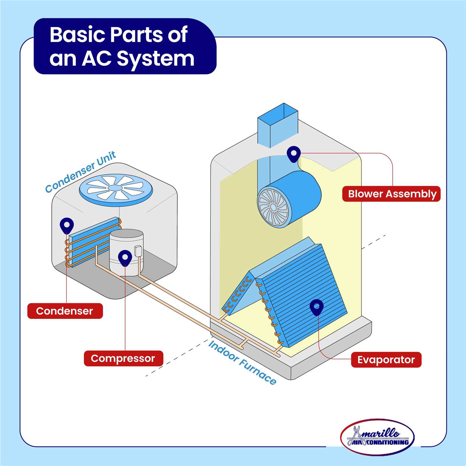
In the realm of air conditioning, a comprehensive understanding of the various elements is crucial for effective maintenance and troubleshooting. Each component plays a vital role in ensuring optimal performance and efficiency of the entire system.
Visual representations serve as invaluable tools for technicians and enthusiasts alike, enabling them to navigate the intricate network of connections and functionalities. By examining these illustrations, one can delve deeper into the workings of their cooling unit.
Ultimately, familiarizing oneself with the layout and relationships between different components can lead to more informed decisions regarding repairs and enhancements, paving the way for a more efficient and reliable air conditioning experience.
Understanding AC Parts Diagrams
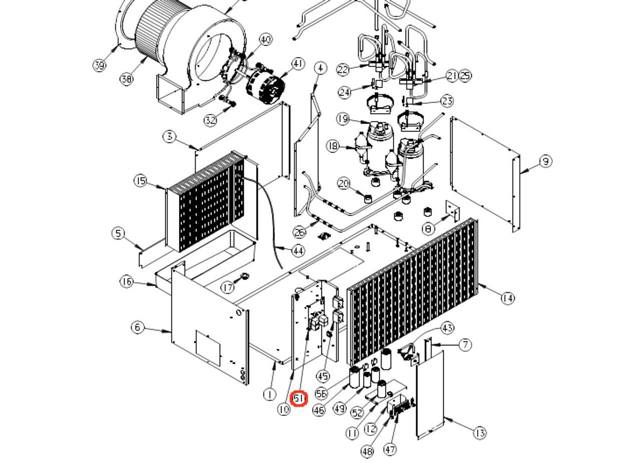
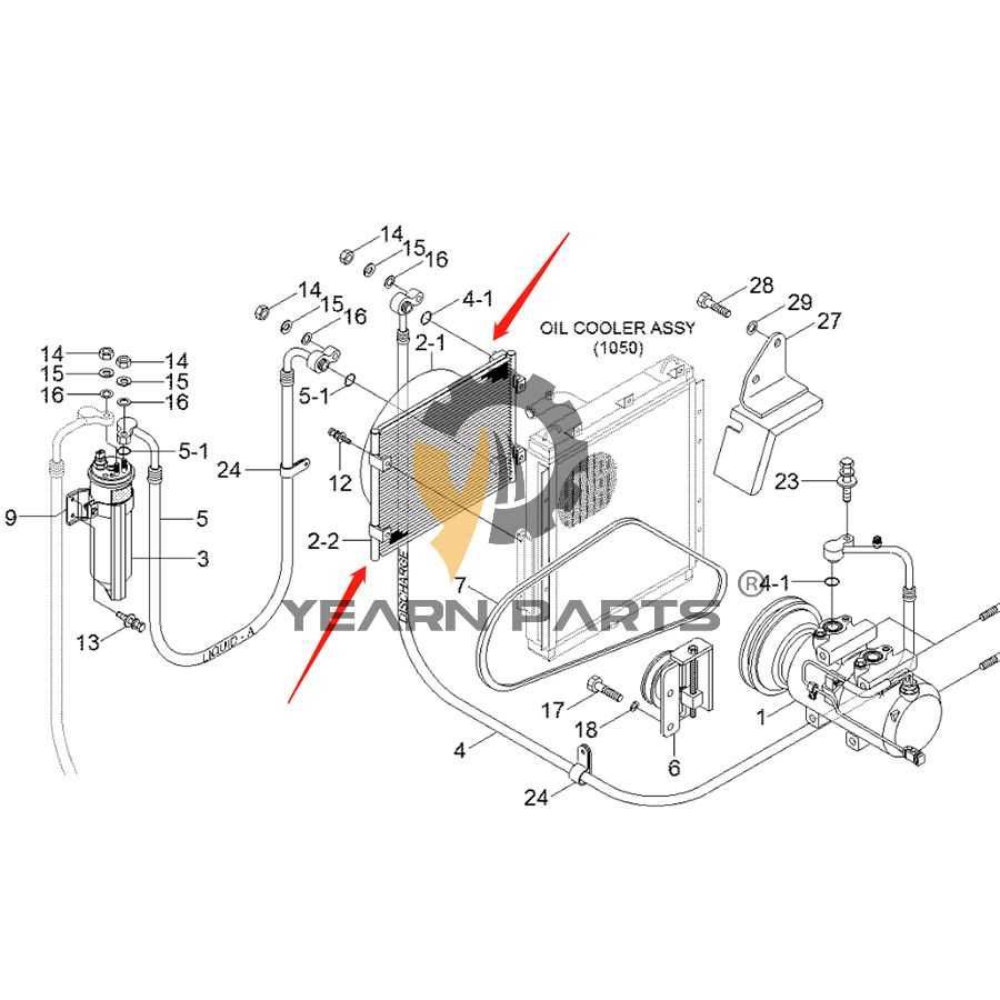
AC systems consist of various components that work in unison to ensure efficient operation. Grasping how these elements interact is crucial for maintenance and troubleshooting.
Key elements include:
- Compressors
- Condenser units
- Evaporators
- Expansion valves
- Refrigerant lines
Comprehending the layout of these components can enhance your ability to diagnose issues. Consider the following steps for effective analysis:
- Identify each component’s role in the system.
- Trace the flow of refrigerant throughout the cycle.
- Understand the connections between different elements.
Ultimately, this knowledge fosters a deeper appreciation of how AC systems function, allowing for informed decisions during repairs and upgrades.
Components of Air Conditioning Systems
Air conditioning systems consist of various elements that work together to provide a comfortable indoor environment. Each component plays a vital role in ensuring efficient temperature regulation and air quality control. Understanding these integral parts can enhance awareness of system functionality and maintenance needs.
The compressor is often regarded as the heart of the system, responsible for circulating refrigerant and facilitating heat exchange. Next, the condenser cools the refrigerant after it has absorbed heat from inside the space, allowing it to release this heat outdoors. The evaporator, conversely, absorbs heat from the indoor air, leading to a drop in temperature and creating a refreshing atmosphere.
Additionally, the expansion valve regulates refrigerant flow, maintaining optimal pressure within the system. The fan circulates air throughout the space, ensuring that cooled air reaches every corner. Filters are crucial for trapping dust and allergens, contributing to healthier indoor air quality.
Overall, these components collaboratively operate to achieve the ultimate goal of comfort, making awareness of their functions essential for effective air conditioning system management.
Importance of Accurate Diagrams
Precision in visual representations is crucial for effective communication and understanding within any technical field. Accurate illustrations serve as essential tools, ensuring that complex information is conveyed clearly, reducing the risk of misinterpretation. When individuals rely on these visuals, they are better equipped to perform tasks efficiently and safely.
One of the key benefits of high-quality visuals is their role in enhancing learning and retention. Clear and well-structured representations help individuals grasp intricate concepts, allowing them to apply their knowledge practically. This is especially important in industries where technical proficiency is critical.
| Benefits | Explanation |
|---|---|
| Improved Clarity | Clear visuals minimize confusion and enhance comprehension. |
| Efficient Problem-Solving | Accurate illustrations provide a reliable reference for troubleshooting and maintenance. |
| Enhanced Collaboration | Visuals facilitate communication among team members, ensuring everyone is on the same page. |
| Increased Safety | Clear representations can highlight potential hazards and safety protocols. |
Ultimately, the significance of precise visuals cannot be overstated. They are foundational elements that support effective operation and ensure that all stakeholders have a clear understanding of the task at hand.
Common Symbols in AC Diagrams
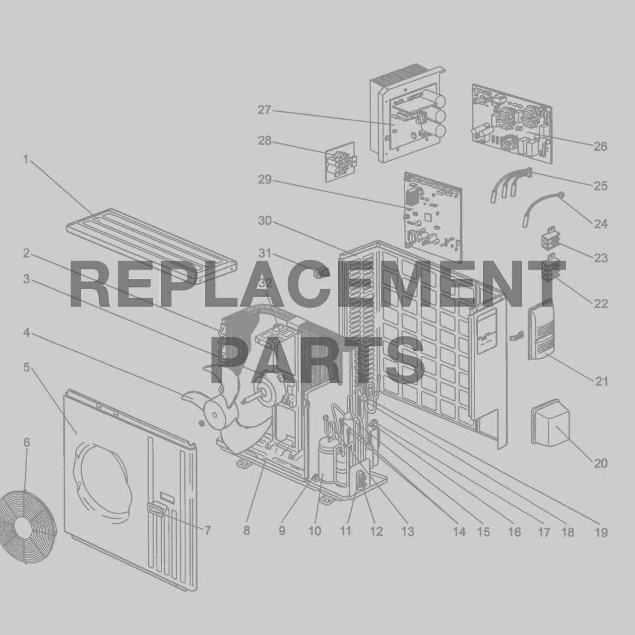
Understanding the representation of components in alternating current systems is essential for efficient analysis and troubleshooting. Various symbols serve to illustrate the functionality and relationships between elements within these electrical frameworks.
Key Symbols
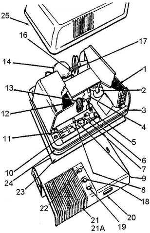
- Transformer: Depicted as two coils, it signifies voltage transformation.
- Capacitor: Represented by parallel lines, indicating energy storage capabilities.
- Inductor: Shown as a series of loops, it denotes magnetic field generation.
- Resistor: Illustrated by a zigzag line, highlighting energy dissipation.
Additional Notations
- Ground: Symbolized by three horizontal lines, indicating a reference point.
- Switch: Often depicted as a break in a line, representing control over the current flow.
- Voltage Source: Shown as a circle with a plus and minus sign, denoting electrical potential.
How to Read AC Wiring Schematics
Understanding electrical schematics is essential for anyone working with alternating current systems. These visual representations illustrate how components are interconnected and provide crucial information about electrical flow. Grasping the symbols and layout used in these illustrations can greatly enhance your ability to troubleshoot and maintain AC systems effectively.
To interpret these representations, it’s important to familiarize yourself with common symbols and their meanings. Each symbol corresponds to a specific component, and recognizing these can simplify the reading process. The layout usually follows a standard convention, making it easier to understand the overall structure.
| Symbol | Component |
|---|---|
| ☐ | Switch |
| ⚡ | Power Source |
| ➰ | Transformer |
| ⏚ | Ground |
Additionally, pay attention to the flow of the circuit, which is often indicated by arrows. These can guide you through the various paths that electricity may take. Understanding the flow is crucial for diagnosing issues, as it allows you to pinpoint where a malfunction may be occurring.
Lastly, practice is key. Reviewing multiple schematics will help you become more proficient and confident in your abilities to read and interpret these valuable resources. With time, you will find that navigating these illustrations becomes an intuitive part of working with AC systems.
Step-by-Step Assembly Instructions
This section provides a clear guide for assembling components efficiently and accurately. By following these detailed directions, you’ll ensure a seamless construction process, resulting in a fully functional unit.
Preparation Before Assembly
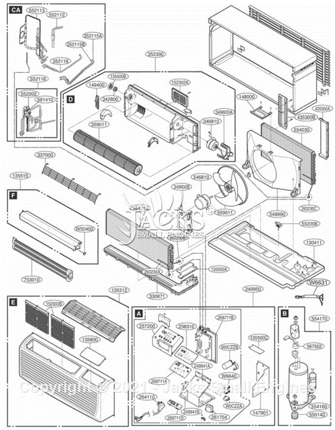
Before starting the assembly, gather all necessary tools and materials. Organizing your workspace will streamline the process, allowing for easier access to items as you progress.
Assembly Steps
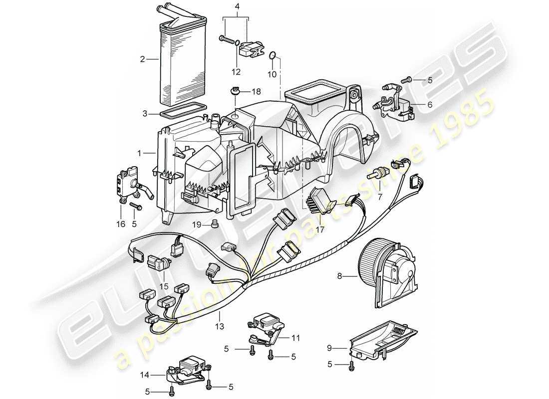
Follow these sequential steps to achieve the best results:
| Step | Description |
|---|---|
| 1 | Begin by securing the foundation pieces, ensuring stability. |
| 2 | Attach the framework components, aligning them carefully. |
| 3 | Integrate the functional elements, checking for compatibility. |
| 4 | Final adjustments and securing all connections should be made. |
By adhering to these steps, you can ensure a successful assembly, culminating in the ultimate functionality of your project.
Troubleshooting Using Diagrams
Effective problem resolution often relies on visual representations that illustrate complex systems. These illustrations provide a clear roadmap, enabling technicians and enthusiasts alike to pinpoint issues more efficiently. By utilizing these graphical tools, one can simplify the diagnostic process, ensuring that each component’s role is understood and assessed accurately.
When facing malfunctions, a systematic approach using these visuals can highlight potential areas of concern. Identifying connections and interdependencies allows for a targeted examination, reducing the time spent searching for the root cause. Moreover, visual aids enhance communication among team members, fostering collaboration and knowledge sharing during troubleshooting efforts.
Incorporating these resources into your diagnostic routine can significantly improve accuracy. By cross-referencing symptoms with the depicted layout, users can eliminate guesswork and focus on the most likely culprits. This method not only saves time but also minimizes the risk of overlooking critical details that could complicate the repair process.
Differences Between Diagrams and Manuals
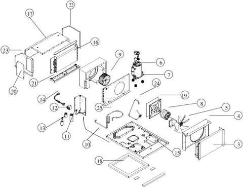
Understanding the distinctions between visual representations and instructional guides is essential for effective communication in technical fields. Each serves a unique purpose, catering to different aspects of user needs and understanding.
Visual aids typically focus on providing a clear picture of components and their arrangement, whereas instructional documents offer detailed procedures and explanations. Here are some key differences:
- Purpose:
- Visual aids aim to illustrate the layout and connections of elements.
- Instructional documents provide step-by-step guidance for assembly or repair.
- Format:
- Visuals often employ images, symbols, and color codes to convey information quickly.
- Guides typically consist of text, bullet points, and numbered lists to facilitate comprehension.
- Detail Level:
- Visual representations may highlight key areas but lack extensive explanations.
- Instructional guides delve into specifics, addressing potential questions and providing context.
- User Interaction:
- Visuals are often more intuitive, allowing users to grasp concepts at a glance.
- Guides require users to read and interpret information, which can enhance understanding through detail.
In summary, while both forms of documentation are vital in their own right, they complement each other by addressing different aspects of user interaction with complex systems.
Benefits of Digital AC Diagrams
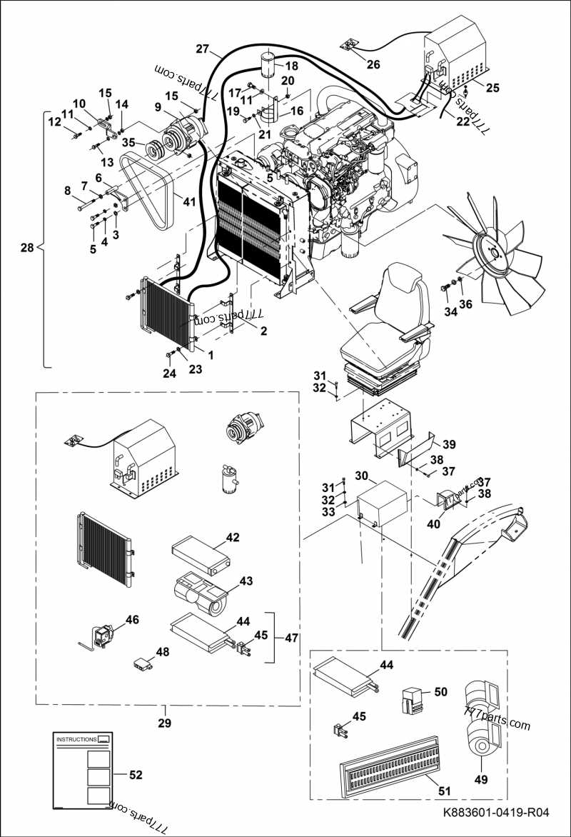
In today’s world, the transition from traditional representations to digital formats has transformed how we interact with technical information. This evolution enhances clarity and accessibility, making it easier for both professionals and enthusiasts to understand complex systems.
Enhanced Clarity and Understanding
Digital representations provide a streamlined view, allowing users to quickly grasp the relationships and functions of various components. This clarity not only reduces the time spent interpreting information but also minimizes errors during assembly and maintenance.
Increased Accessibility and Convenience

With the rise of digital formats, users can access information from anywhere, at any time. This convenience empowers individuals to delve into details and find the ultimate solutions for troubleshooting or upgrades, significantly enhancing the overall efficiency of their work.
How to Create Your Own Diagram
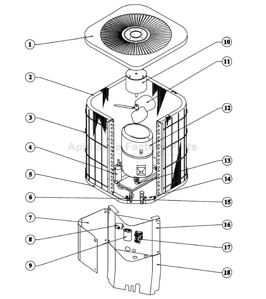
Designing a visual representation of components can greatly enhance understanding and communication. This process allows for the clear illustration of relationships and functions, making complex information accessible and easier to interpret.
Step-by-Step Guide
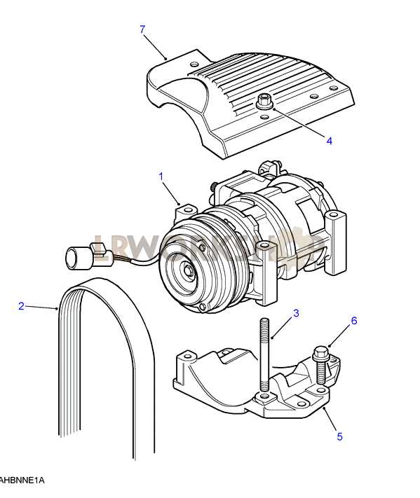
To start, gather all necessary information regarding the items you wish to represent. Organizing this data will help in structuring your visual layout effectively.
Tools and Techniques
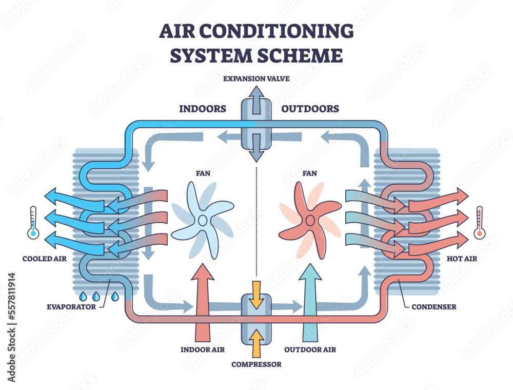
Utilize software or online platforms that facilitate the creation of visuals. These tools often provide templates and features to streamline your workflow.
| Tool | Features | Best For |
|---|---|---|
| Lucidchart | Drag-and-drop interface | Collaborative projects |
| Draw.io | Free and open-source | Basic diagrams |
| Visio | Advanced functionalities | Professional layouts |
Resources for Finding AC Diagrams
Locating accurate schematics for air conditioning systems is crucial for both professionals and DIY enthusiasts. Numerous resources can aid in this quest, providing valuable information that simplifies repairs and maintenance. Below are some recommended avenues to explore.
- Manufacturer Websites: Most manufacturers offer a wealth of technical documents, including schematics. Visit the official site of your AC unit’s brand for user manuals and service guides.
- Online Forums: Communities of HVAC technicians and enthusiasts often share insights and diagrams. Websites like Reddit or specialized HVAC forums can be great places to ask questions and find shared resources.
- Technical Manuals: Professional-grade manuals are available for purchase or through libraries. These documents typically include detailed illustrations that cover various models.
- YouTube Tutorials: Many technicians create video content that outlines troubleshooting and repair processes, often showcasing schematics in the process. A visual approach can enhance understanding.
- HVAC Educational Websites: Platforms dedicated to HVAC education often have downloadable resources. Look for reputable sites that provide comprehensive guides and schematics for learners.
By leveraging these resources, users can enhance their understanding and effectively address issues with air conditioning systems.
Maintaining Your AC System Effectively
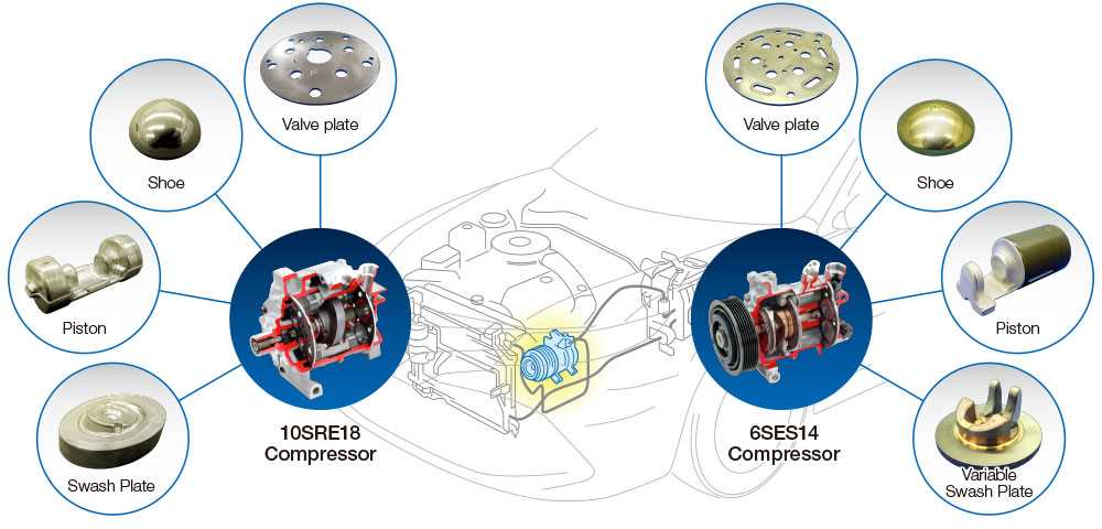
Proper upkeep of your air conditioning unit is essential for ensuring optimal performance and longevity. Regular maintenance not only enhances efficiency but also helps in preventing unexpected breakdowns. By implementing a few key practices, you can keep your cooling system in top shape and enjoy a comfortable indoor environment year-round.
Key Maintenance Practices
There are several critical tasks that should be performed regularly to maintain your cooling system. These include cleaning, inspecting, and replacing various components as needed. Adopting a proactive approach can lead to significant savings on energy costs and repair expenses.
| Task | Frequency | Description |
|---|---|---|
| Filter Replacement | Every 1-3 months | Replace or clean filters to ensure proper airflow and improve efficiency. |
| Coil Cleaning | Annually | Clean the evaporator and condenser coils to remove dirt and debris that hinder performance. |
| Drain Line Check | Every 6 months | Inspect and clear the condensate drain line to prevent water damage and mold growth. |
| Professional Inspection | Annually | Schedule a comprehensive inspection by a qualified technician to identify potential issues. |
Benefits of Regular Maintenance
Regular attention to your air conditioning unit brings a host of advantages. Improved efficiency leads to lower energy consumption, and a well-maintained system operates more quietly. Additionally, routine check-ups can extend the lifespan of your equipment, providing peace of mind and ensuring comfort throughout the seasons.