Modern cordless tools have become an essential part of various industries and daily tasks. To maintain their efficiency, it’s crucial to grasp how each component functions and how they connect to form a unified, well-performing system. This guide will walk you through the key elements that ensure smooth operation and reliable performance, focusing on the internal structure of a popular model.
The breakdown of these essential elements provides valuable insights into how various parts work together to deliver power and precision. Whether you’re looking to repair, upgrade, or simply understand how the tool operates, this information can help you identify and address any potential issues.
In the following sections, we’ll explore the intricate design of these tools, highlighting the main features and providing a clear overview of their functional roles. This understanding can assist with both troubleshooting and improving overall performance.
Components Overview
Understanding the key elements of this powerful tool is crucial for maximizing its efficiency. Each piece plays a specific role, ensuring smooth performance and durability. Below is a breakdown of the main components that contribute to its functionality.
- Motor – The core element that drives the overall operation, offering high speed and consistent performance.
- Grip Handle – Designed for user comfort, providing a secure and steady hold during usage.
- Trigger – Enables precise control over the speed and power, making it easier to manage different tasks.
- Belt Clip – A convenient feature that allows for easy carrying and accessibility when not in use.
- LED Light – Helps illuminate the work area, improving visibility in low-light conditions.
- Battery Slot – A key area where the power source is connected, allowing for quick swaps during extended tasks.
Each of these components is carefully engineered to provide a balance of power, precision, and ease of use.
Internal Structure of the DCF886 Model

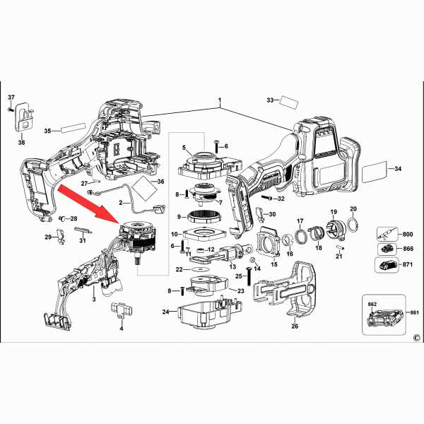
The design of this model is crafted with efficiency in mind, ensuring both durability and optimal performance. Inside, the arrangement of essential components forms a well-balanced system that delivers high functionality and power. Understanding how these internal elements work together provides insight into the overall performance of the device.
Main Mechanical Components
The core of the tool consists of a powerful motor connected to a robust gear system. These mechanical parts are responsible for generating the necessary force and speed, ensuring smooth operation. The motor’s integration with the gear assembly creates a fluid transition of power, minimizing energy loss and enhancing productivity.
Electronic Control System
The electronic control unit plays a critical role in managing power distribution. It adjusts the device’s performance based on the workload, allowing for precise control and energy efficiency. This system includes advanced sensors that ensure smooth operation under different conditions, contributing to the overall longevity of the device.
Battery and Charger Compatibility Guide
Choosing the right combination of power sources and charging devices is crucial for ensuring efficient and long-lasting performance of your tools. This guide provides key insights into understanding which power cells and charging units work seamlessly together, ensuring smooth operation and reliability in a variety of tasks.
Power Source Selection: When selecting a power cell, it’s important to consider capacity, voltage, and technology. Some models are equipped with advanced features that enhance longevity, while others offer faster energy delivery for demanding tasks. Identifying the right match can improve both efficiency and lifespan.
Charger Compatibility: Not all charging stations are designed to work with every power cell. Ensuring compatibility is essential to prevent damage and optimize charging times. Modern charging units often feature smart technology, allowing for more controlled and safer energy transfer.
Pro Tip: Always check the manufacturer’s guidelines to verify that the selected power cell and charging unit are compatible with each other and the specific tools you are using.
Understanding the Motor Assembly
The motor assembly is one of the core components responsible for driving performance in many power tools. It consists of several interconnected parts working together to convert electrical energy into mechanical force. Grasping the structure and role of each element within this assembly helps ensure efficient operation and long-term durability.
Main Components of the Motor
The motor is made up of several critical elements, each contributing to its function. The rotor, stator, and brushes work in tandem to create the rotational motion needed for tool functionality. Their alignment and condition directly influence overall efficiency.
Key Interactions within the Assembly
Understanding how each component interacts is vital for maintenance and repairs. The rotation of the rotor within the magnetic field generated by the stator, combined with the contact of the brushes, creates the torque required for operation. Proper lubrication and alignment play a key role in ensuring smooth functionality.
| Component | Function | |||||||||||||||||||||||||||
|---|---|---|---|---|---|---|---|---|---|---|---|---|---|---|---|---|---|---|---|---|---|---|---|---|---|---|---|---|
| Rotor | Converts electrical energy into mechanical motion. | |||||||||||||||||||||||||||
| Stator | Generates a magnetic field that drives the rotor. | |||||||||||||||||||||||||||
| Brushes |
| Component | Function | ||||||||||||||||||||||
|---|---|---|---|---|---|---|---|---|---|---|---|---|---|---|---|---|---|---|---|---|---|---|---|
| Trigger | Controls speed based on pressure applied | ||||||||||||||||||||||
| Control Unit | Housing and Exterior Parts Breakdown
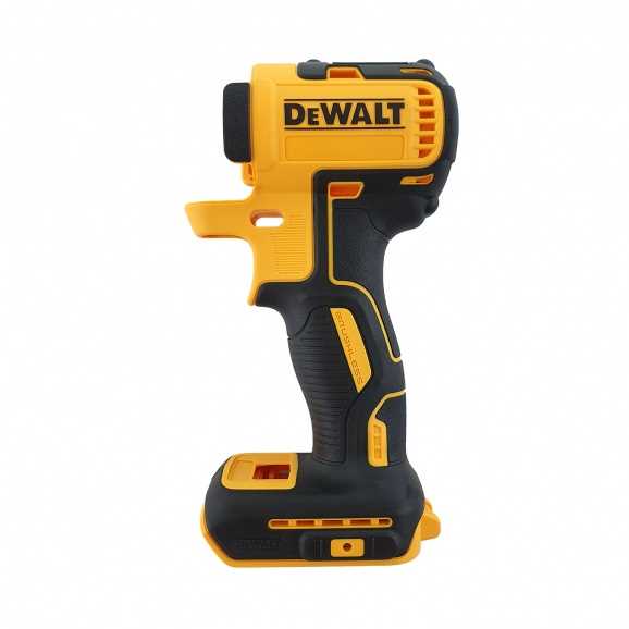
The structural components and outer elements of a tool play a crucial role in its overall functionality and durability. Understanding these features helps users maintain and troubleshoot their equipment effectively. Key Outer Elements
Assembly Considerations
Commonly Replaced Parts for DCF886When it comes to maintaining tools, certain components tend to require replacement more frequently than others. Understanding which elements are commonly swapped out can enhance the longevity and performance of your equipment. This section explores those frequently replaced components, highlighting their significance in ensuring optimal functionality.
Proper Maintenance of Key Components
Ensuring the longevity and optimal performance of essential parts in power tools requires diligent upkeep. Regular attention to these elements can prevent premature wear and enhance functionality. Adopting a systematic approach to maintenance is crucial for any user aiming to maximize the efficiency of their equipment. Regular Cleaning is fundamental. Accumulated dust and debris can obstruct moving parts, leading to decreased efficiency and potential damage. Use a soft brush or compressed air to remove particles from the tool’s exterior and interior components, ensuring that every crevice is attended to. Lubrication plays a vital role in maintaining smooth operation. Apply suitable lubricants to moving parts as recommended in the manufacturer’s guidelines. This reduces friction and wear, promoting a longer lifespan for these crucial elements. Periodic Inspection is essential for identifying potential issues before they escalate. Examine all components for signs of damage, wear, or misalignment. Addressing these concerns promptly can save time and money in the long run, ensuring reliable performance during use. By adhering to these maintenance practices, users can significantly improve the reliability and efficiency of their power tools, fostering a productive and safe working environment. Brushless Technology in Dewalt ToolsBrushless technology represents a significant advancement in power tool design, enhancing performance and efficiency. This innovative approach eliminates the traditional brushes found in conventional motors, leading to improved energy utilization and reduced wear. The result is a longer lifespan for the tool and increased runtime for battery-operated devices. Benefits of Brushless MotorsTools equipped with brushless motors offer numerous advantages over their brushed counterparts. These include:
Applications of Brushless TechnologyThis modern technology is increasingly found in various applications, including construction, woodworking, and automotive tasks. By providing greater power and efficiency, tools featuring this technology are ideal for professionals and DIY enthusiasts alike, allowing for more effective and precise work. Tips for Assembling and DisassemblingWhen working with power tools, understanding the process of putting together and taking apart components is essential for effective maintenance and repair. This section provides useful guidelines to ensure a smooth experience while handling various elements of your device.
By following these suggestions, you can enhance your efficiency and ensure the longevity of your equipment. Troubleshooting with the Parts DiagramEffective troubleshooting relies on a comprehensive visual representation of a tool’s components. Such an illustration serves as a vital resource, allowing users to identify and address issues efficiently. By consulting this guide, individuals can pinpoint specific areas that may require attention. Identifying Common Issues: Many problems can arise from wear and tear or misalignment of parts. Utilizing the visual guide enables users to recognize these common challenges, facilitating a quicker resolution process. Understanding Component Functionality: Each element within the illustration plays a unique role in the overall operation of the tool. Familiarity with how these components interact helps users diagnose problems accurately, ensuring effective repairs and maintenance. Streamlining Repair Processes: Access to a detailed visual reference simplifies the repair process, allowing for swift identification of necessary replacements. This efficiency not only saves time but also enhances the tool’s longevity. |
