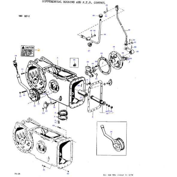
Differential: This component helps in distributing power between the wheels, especially when turning. It ensures each wheel can rotate
Exploring the Cooling System Diagram
The cooling system is essential for maintaining optimal engine performance by managing temperature levels during operation. A clear understanding of its components and their arrangement can help in ensuring efficient heat dissipation and preventing potential overheating issues.
Main Components of the Cooling Setup
- Radiator: The primary element responsible for dispersing heat, utilizing coolant to transfer warmth away from the engine.
- Water Pump: Circulates the coolant through the system, ensuring consistent flow between the engine and the radiator.
- Thermostat: Monitors the temperature and regulates the coolant’s path to maintain optimal thermal conditions.
Understanding the Flow Process
Key Elements of the Electrical Wiring Layout

The electrical wiring configuration of any machinery is crucial for its optimal functioning and reliability. Understanding the key components of this layout is essential for effective maintenance and troubleshooting. Each segment plays a significant role in ensuring that power is efficiently distributed and that various systems operate harmoniously.
Fundamental Components
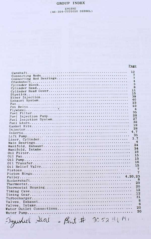
At the heart of any wiring system are the various connectors and terminals that facilitate electrical connections. Wires themselves come in different gauges, affecting their capacity to carry current. The switches integrated into the system allow users to control different functions, while fuses provide necessary protection against overcurrent situations.
Layout Considerations
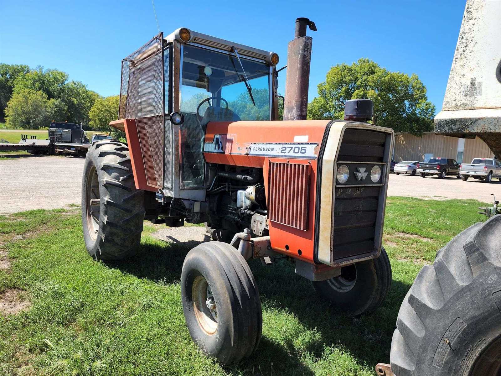
When designing the wiring layout, it is essential to consider factors such as circuit routing and grounding. Proper routing minimizes the risk of interference and damage, while effective grounding ensures safety and stability. Additionally, the use of color-coded wires helps in easy identification and troubleshooting, streamlining maintenance efforts significantly.
Guide to Fuel System Components
The fuel system is a crucial part of any engine, responsible for delivering the necessary energy for optimal performance. Understanding its various components can help ensure efficient operation and maintenance. This section will provide an overview of the essential elements found within a typical fuel system, highlighting their functions and importance in the overall machinery.
Key Elements of the Fuel System
Fuel systems comprise several vital components that work together to manage fuel delivery, pressure, and filtration. Each part plays a specific role in ensuring that the engine receives a consistent and clean supply of fuel. Here are the primary components:
| Component |
Description |
| Fuel Tank |
The reservoir that holds the fuel before it is sent to the engine. |
| Fuel Pump |
A device that moves fuel from the tank to the engine, maintaining the necessary pressure. |
| Fuel Filter |
Removes impurities and contaminants from the fuel to protect the engine. |
| Injectors |
Atomize the fuel for better combustion efficiency within the engine. |
| Pressure Regulator |
Maintains a consistent fuel pressure to the injectors, ensuring optimal performance. |
Maintaining Fuel System Efficiency
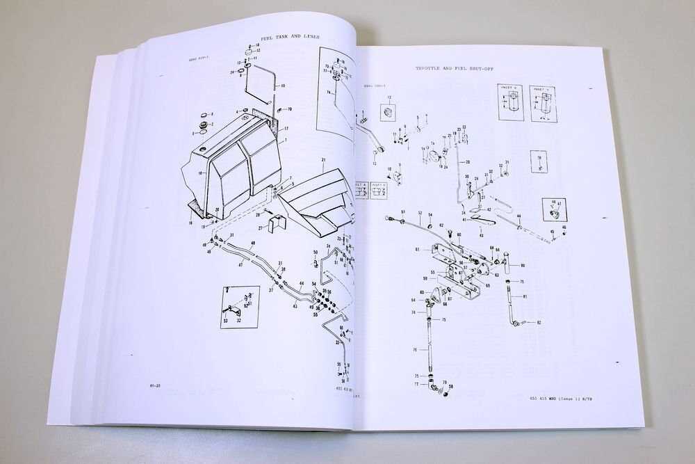
Regular maintenance of the fuel system components is essential for prolonging engine life and maintaining performance. This includes timely replacement of filters, ensuring the pump operates effectively, and checking for any leaks in the system. By adhering to these practices, operators can avoid costly repairs and ensure their machinery runs smoothly.
Examining the Steering Mechanism Parts
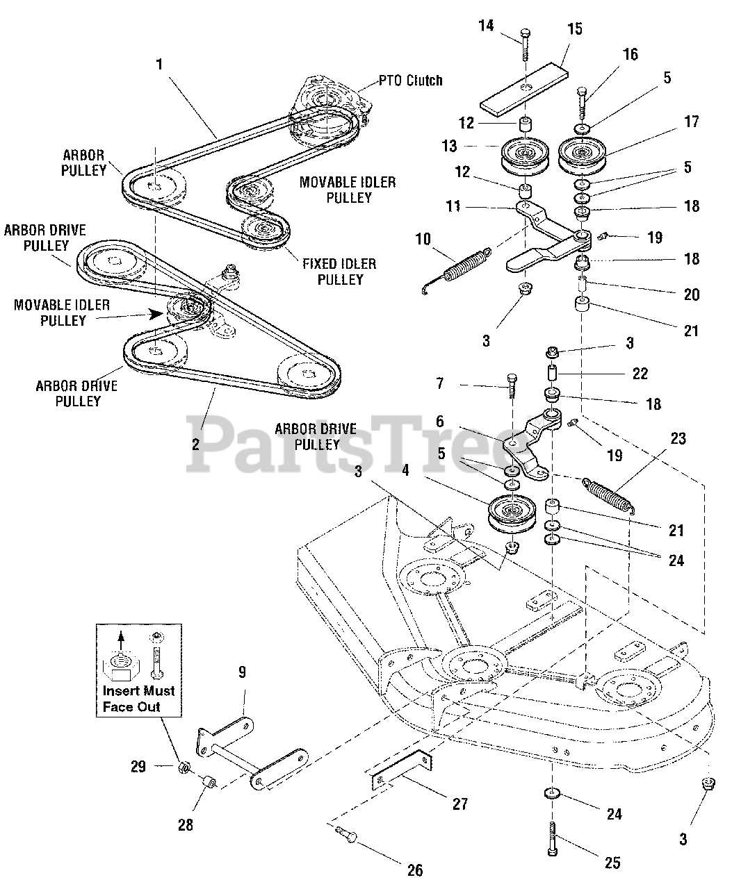
The steering system is a critical component of any agricultural vehicle, providing essential control and maneuverability. Understanding its individual elements can enhance maintenance practices and improve operational efficiency. This section will delve into the key components involved in the steering mechanism, exploring their functions and importance within the overall system.
Key Components of the Steering System
Several integral components work together to ensure smooth and responsive steering. Each part plays a vital role in transmitting the driver’s input to the wheels effectively. Here is an overview of these crucial elements:
| Component |
Description |
| Steering Wheel |
The primary control mechanism for directing the vehicle’s movement. |
| Steering Column |
Connects the steering wheel to the steering gear, allowing for smooth rotation. |
| Steering Gear |
Converts the rotational motion of the steering wheel into linear motion. |
| Linkage |
Transmits force from the steering gear to the wheels, enabling directional changes. |
| Ball Joints |
Facilitate movement between the steering linkage and wheel assemblies. |
Maintenance Tips for Steering Components
Regular inspection and maintenance of the steering mechanism are crucial for optimal performance. Key practices include checking for wear and tear, ensuring proper lubrication, and verifying alignment. Addressing any issues promptly can prevent larger problems and enhance the lifespan of the steering system.
Overview of Brake System Configuration
The braking mechanism is a critical component in ensuring the safety and efficiency of agricultural machinery. Its design integrates various elements that work together to provide reliable stopping power, essential for operating in diverse conditions. Understanding the configuration of the braking system can enhance maintenance practices and improve overall vehicle performance.
This braking assembly typically includes several key components, each serving a specific function. The interplay between these parts ensures that the system responds effectively to operator commands while maintaining stability during operation.
| Component |
Description |
| Brake Pedal |
Controls the braking action when pressed by the operator. |
| Brake Cylinder |
Generates hydraulic pressure to activate the braking mechanism. |
| Brake Linings |
Friction material that contacts the brake drum to slow down the vehicle. |
| Brake Drum |
The component where the brake linings engage to create friction. |
| Hydraulic Lines |
Convey hydraulic fluid between components to enable braking. |
Regular inspection and maintenance of this configuration are vital to ensure effective operation. Proper care can prevent common issues such as wear and overheating, ultimately extending the lifespan of the braking system.
Rear Axle and Differential Parts Description
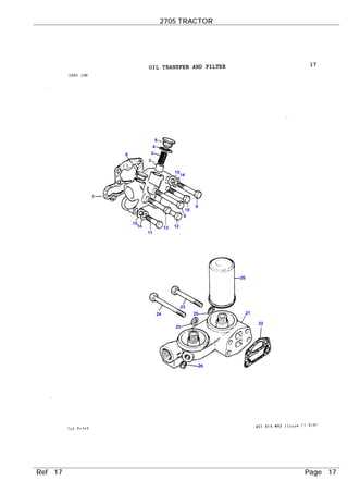
The rear axle and differential assembly play a crucial role in the overall functionality of agricultural machinery. These components are essential for transferring power from the engine to the wheels, allowing for smooth movement and effective torque distribution. Understanding the various elements within this assembly is vital for proper maintenance and operation.
The rear axle consists of several key elements, including the axle housing, which provides structural integrity and support. Inside the housing, you’ll find the axle shafts, which connect to the wheels, enabling them to rotate. Additionally, bearings are employed to facilitate smooth rotation and minimize friction.
The differential is another critical component, responsible for allowing the wheels to rotate at different speeds, especially during turns. This mechanism includes gears and a casing that houses them, ensuring efficient power distribution while maintaining traction. Regular inspection and maintenance of these components are essential to prevent wear and ensure optimal performance.
Cabin Controls and Instrumentation Layout

The arrangement of controls and instrumentation within the operator’s compartment plays a crucial role in enhancing the efficiency and safety of agricultural machinery. A well-designed layout ensures that all necessary functions are within easy reach, allowing for seamless operation while minimizing distractions. This section explores the key elements involved in the control setup, highlighting their significance in everyday tasks.
Control Configuration
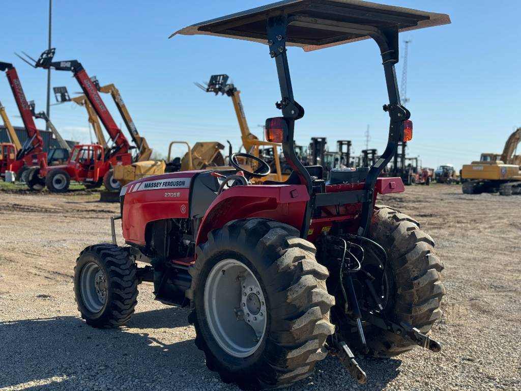
In any agricultural vehicle, the control configuration is essential for optimal user interaction. The placement of levers, switches, and dials is designed to facilitate quick access and intuitive use. Ergonomically positioned controls allow operators to respond promptly to changing conditions, ensuring smooth performance and increased productivity.
Instrumentation Overview
The instrumentation panel provides vital information regarding the machinery’s operation, such as speed, fuel levels, and engine temperature. Clear visibility of these indicators is crucial for effective monitoring and decision-making. Moreover, the layout is designed to minimize glare and distractions, enabling operators to focus on their tasks while maintaining awareness of critical metrics.
Power Take-Off (PTO) Assembly Structure
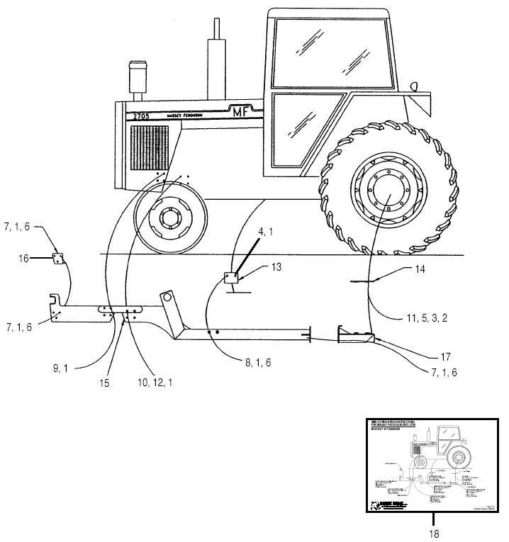
The Power Take-Off (PTO) system is a crucial component in agricultural machinery, designed to transfer mechanical energy from the engine to various implements. Understanding its assembly structure is essential for maintenance and operation, ensuring efficient power transmission and reliability in fieldwork.
This assembly typically comprises several key elements that work in unison. Each part plays a vital role in the overall functionality of the system, allowing for seamless integration with different attachments.
| Component |
Description |
| Input Shaft |
The main shaft that receives power from the engine and transfers it to the PTO assembly. |
| Clutch Assembly |
Facilitates engagement and disengagement of power flow, allowing for control over implement operation. |
| PTO Gearbox |
Changes the speed and direction of power, ensuring compatibility with various attachments. |
| Output Shaft |
Delivers power to the implement, designed to connect securely and withstand operational stresses. |
| Safety Guard |
Protects the user from moving parts and prevents accidental contact during operation. |
Regular inspection and maintenance of these components are essential to avoid operational failures and prolong the life of the machinery. Proper knowledge of the assembly structure aids in troubleshooting and effective repairs.
Front and Rear Wheel Assembly Diagram
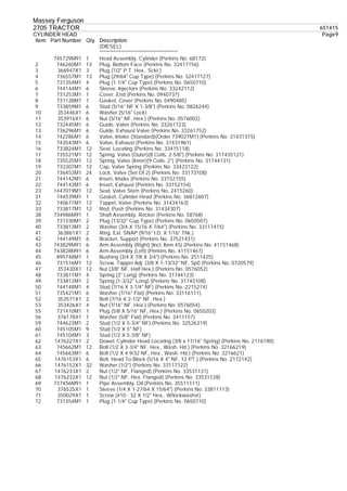
This section provides a detailed overview of the wheel assembly components for agricultural machinery. Understanding the arrangement and function of these elements is crucial for effective maintenance and troubleshooting.
The following table outlines the various components that constitute the wheel assembly, along with their respective functions:
| Component |
Description |
| Hub |
The central part that connects the wheel to the axle, enabling rotation. |
| Rim |
The outer circular part that holds the tire in place. |
| Tire |
The rubber component that provides traction and absorbs shock. |
| Spokes |
Support structures that connect the hub to the rim, ensuring stability. |
| Axle |
The shaft that allows the wheels to rotate and supports the vehicle’s weight. |
| Bearing |
Facilitates smooth rotation of the hub around the axle. |
Familiarity with these components is essential for effective assembly and maintenance, ensuring optimal performance and longevity of the equipment.
