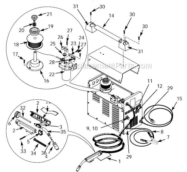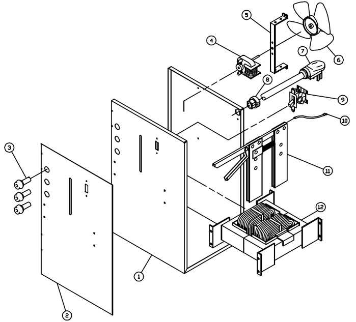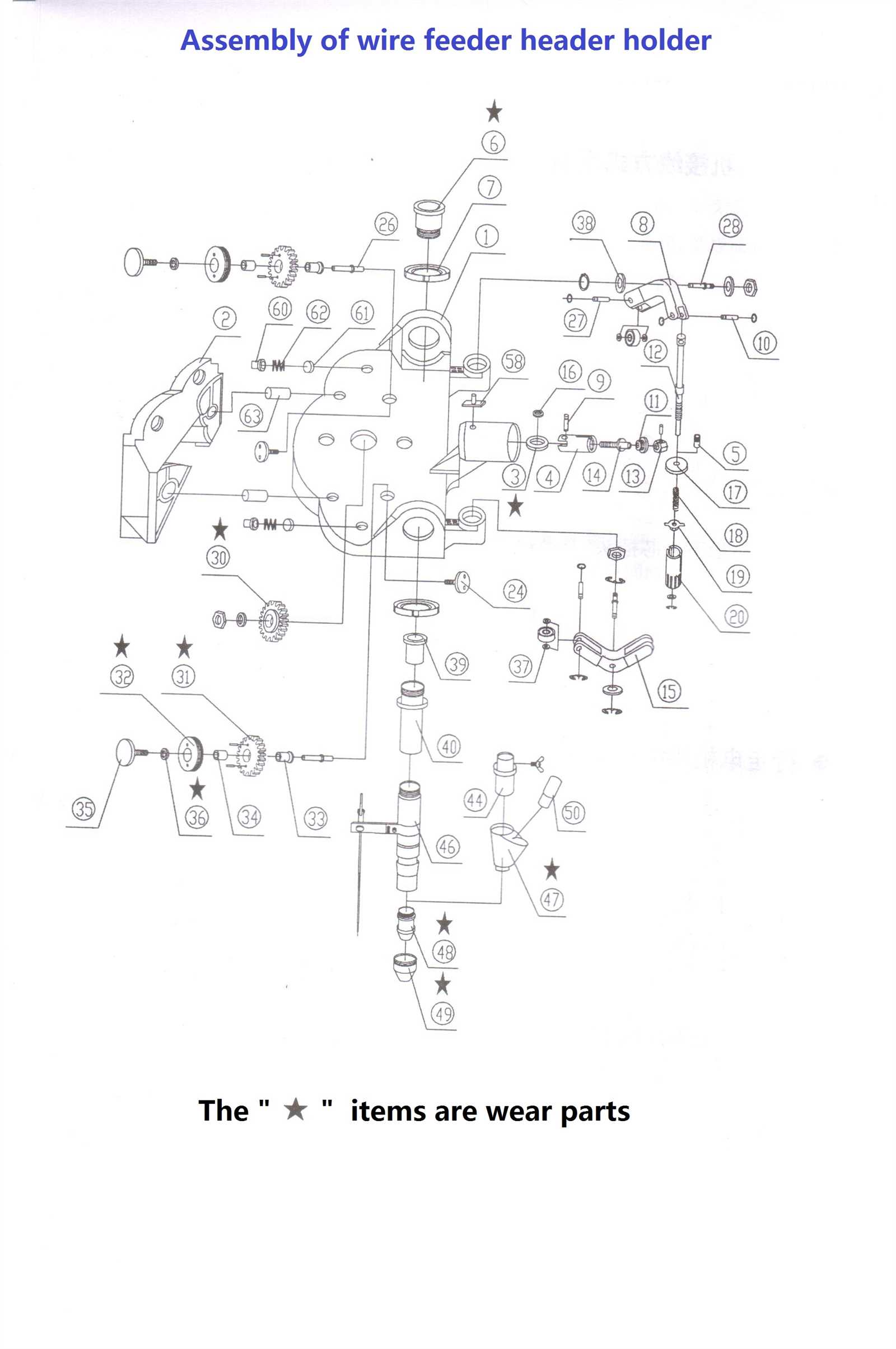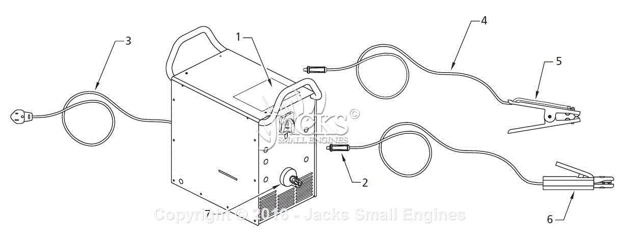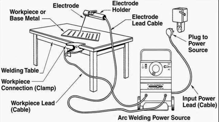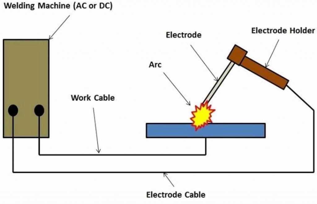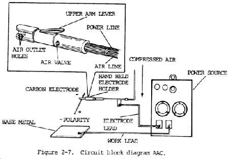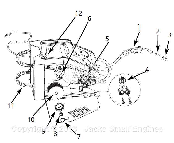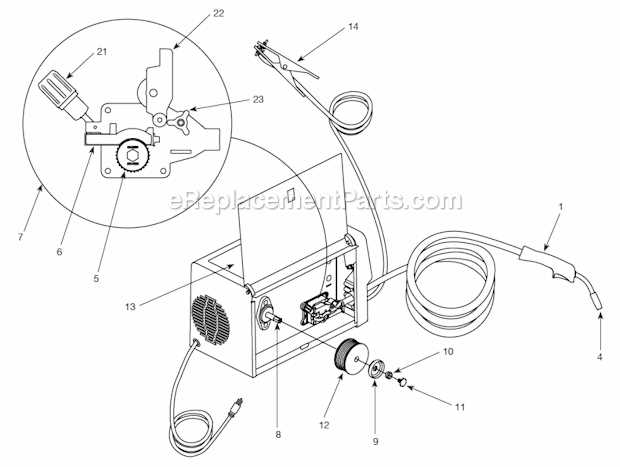
Welding devices are intricate tools made up of various elements that work in harmony to create a seamless and efficient fusion process. The internal workings of these machines are carefully designed to handle high temperatures and electrical currents, ensuring precise and controlled operations.
In this section, we will explore the essential mechanisms that enable these machines to perform their tasks. From controlling energy flow to managing the output, each component plays a vital role in the overall functionality of the device. By gaining insight into how these elements interact, one can better understand the maintenance and troubleshooting of such equipment.
Whether you are maintaining your equipment or simply curious about how it functions, understanding the core elements will provide you with valuable knowledge. Proper care and replacement of these mechanisms ensure longer life and improved performance of your tool.
Arc Welder Internal Components Overview
Understanding the inner structure of electric metal fusion machines provides valuable insight into how these systems work. This section explores the critical elements that make the machine function effectively, focusing on the electrical and mechanical systems that ensure seamless operation.
- Transformer: This device regulates the voltage, converting it into a suitable form for efficient energy transfer.
- Rectifier: Converts alternating current (AC) into direct current (DC), ensuring smooth and consistent power flow.
- Control Board: This unit manages various operations, such as adjusting power levels and monitoring system performance.
- Cooling System: Prevents overheating during operation, extending the lifespan of the machine.
- Power Supply: Provides the necessary energy to initiate and sustain the metal fusion process.
Each of these components plays a crucial role in maintaining the reliability and efficiency of the system, ensuring consistent and high-quality results in metal processing tasks.
Electrode Holder and Its Function
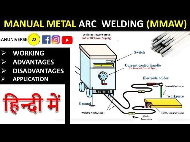
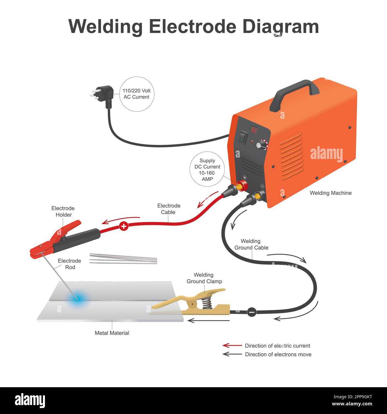
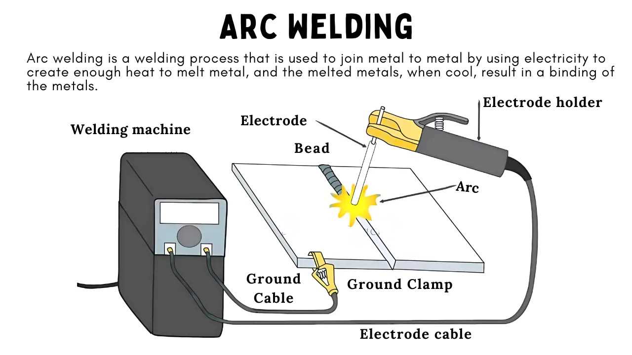
The holder for the electrode plays a crucial role in the overall process of electrical fusion. It is the component responsible for securing the consumable element, ensuring that it remains in the correct position during operation. This tool allows for a stable flow of electricity and provides safety by offering an insulated grip for the operator.
Design and Materials
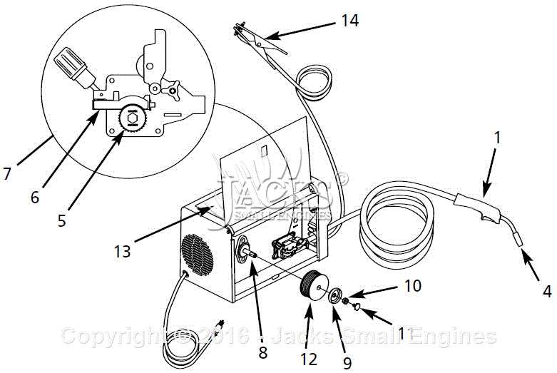
The design of the electrode holder is typically composed of durable, heat-resistant materials. It often features a clamping mechanism that firmly grips the electrode. This structure prevents slippage and allows for easy replacement of the consumable part when needed. Insulation is also a critical feature, protecting the user from electric shock while maintaining comfort and control.
Importance of Proper Handling
Ensuring proper use of the holder enhances both safety and efficiency. A well-designed holder ensures minimal wear on the consumable material and improves the quality of the final result. Additionally, the ergonomic design provides comfort, reducing fatigue during extended use. Proper care and maintenance can extend the lifespan of this essential tool, making it a key component in achieving optimal results.
Power Supply Structure in Welders
The power supply is the backbone of any equipment used for thermal joining processes. It provides the necessary energy for generating heat, which enables the fusion of materials. A well-designed power system ensures consistent performance and contributes to the overall efficiency of the process.
Main Components
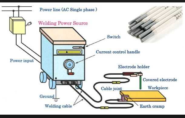
The power supply typically consists of several key components, including transformers, rectifiers, and control circuits. Transformers are responsible for adjusting the voltage levels, while rectifiers convert alternating current (AC) into direct current (DC), which is crucial for steady operations. Control circuits manage the flow and stability of energy to maintain optimal functioning.
Energy Management
Effective energy management is essential for maintaining the quality of the process. This is achieved by regulating voltage and current to match the requirements of different materials and techniques. The design of the power supply plays a significant role in determining the efficiency, with advanced systems providing precise control over the energy output.
How Cooling Systems Work in Welders

Effective temperature management is crucial for maintaining the functionality of high-temperature devices. When operating continuously, these machines generate significant heat, and an efficient cooling solution is essential to prevent overheating and ensure longevity.
The cooling process involves circulating a fluid or using fans to disperse heat away from sensitive components. There are typically two main methods: air-based and liquid-based. Each system has its advantages, depending on the power and usage of the device.
| Cooling Method | Mechanism | Application | ||||||||||||||||||||||||||||||||||||||||||||||
|---|---|---|---|---|---|---|---|---|---|---|---|---|---|---|---|---|---|---|---|---|---|---|---|---|---|---|---|---|---|---|---|---|---|---|---|---|---|---|---|---|---|---|---|---|---|---|---|---|
| Air Cooling | Fans or vents dissipate heat by pushing air over hot surfaces. | Common in smaller or less demanding systems. | ||||||||||||||||||||||||||||||||||||||||||||||
| Liquid Cooling | Coolant circulates through channels, transferring heat to radiators. | Used in more powerful or continuously opera
Understanding the Role of the Ground Clamp
The ground clamp plays a vital role in ensuring efficient and safe operation during metal joining processes. It provides the necessary return path for the electrical current, contributing to a stable and controlled connection between the equipment and the workpiece. Why Proper Grounding MattersWithout a secure connection from the ground clamp, the flow of electricity becomes unstable, leading to irregular results and potentially hazardous situations. A well-functioning clamp ensures consistent energy flow, which is essential for quality performance and safety. Common Ground Clamp Materials
Ground clamps are typically made from conductive metals, which help minimize resistance and promote smooth current transfer. Below is a comparison of the most common materials used in ground clamps:
Transformer Components in Arc WeldingTransformers play a crucial role in the functioning of various welding machines, providing the necessary electrical power for the process. They convert high voltage electricity from the supply into a lower voltage suitable for welding applications, ensuring efficient and safe operation. The essential elements of a transformer in welding equipment include the core, windings, and insulation. Each component is designed to handle specific electrical loads while maintaining reliability and performance. Understanding these components helps users appreciate the intricacies of welding technology and ensures proper maintenance.
Control Panel Parts and Their Use
The control panel of a welding device serves as the central hub for operating and managing the equipment. Understanding its components is essential for efficient and safe operation. Each element plays a significant role in ensuring that the device functions properly and meets the user’s requirements. Key Components
Among the various elements of the control interface, several stand out due to their functionality and importance:
Importance of Each Element
Each component is designed to enhance the user’s experience and ensure safety. For instance, the power switch must be easily accessible to enable quick shut-off in emergencies. Similarly, precise control over voltage and current is crucial for adapting to various tasks and materials, preventing defects and ensuring quality in the welding process. Welding Cables and Connections
The effectiveness of any metal joining process relies heavily on the quality and design of the conductive components used. Proper connections and reliable cables ensure efficient power transmission, which is essential for achieving high-quality results. Understanding the various elements involved in these connections can significantly enhance the performance and safety of the operation. Types of Conductive Wires
Different types of conductive wires are utilized based on the specific requirements of the task. Flexible cables are often favored for their ease of maneuverability, allowing users to work in various positions without restriction. In contrast, heavy-duty cables are preferred for their durability and ability to handle high currents, making them suitable for extensive applications. Connection Methods
Establishing secure connections is critical to prevent energy loss and ensure optimal functionality. Common methods include screw terminals and plug connectors, each offering unique benefits. Screw terminals provide a robust, permanent solution, while plug connectors offer flexibility and ease of disconnection, facilitating quick setup and transport. Rectifiers and Their Importance in Welding
In the realm of metal joining processes, specific components play a crucial role in ensuring optimal performance and efficiency. Among these, certain devices are essential for converting electrical currents, allowing for effective energy management during operation. Understanding their functionality is key to achieving high-quality results in fabrication tasks. Functionality of RectifiersRectifiers serve as critical elements in controlling the flow of electricity. They transform alternating current (AC) into direct current (DC), which is often preferred for various joining applications due to its stability and consistency. This conversion not only enhances the quality of the fusion but also minimizes fluctuations that could lead to defects in the finished product. Impact on Welding ProcessesEmploying rectifiers significantly improves the overall effectiveness of joining operations. With the ability to provide a smooth and controlled current, they enable welders to achieve precise and clean seams. This stability reduces the risk of common issues such as spatter and incomplete fusion, making rectifiers indispensable in modern metalworking. Shielding Gas System in Arc WeldersThe shielding gas system plays a crucial role in the welding process, providing a protective environment that prevents contamination of the molten material. This system ensures that the weld area remains free from harmful atmospheric elements, enhancing the quality and integrity of the joint being formed. Key components of this system include:
Proper setup and maintenance of the shielding gas system are essential for optimal performance. Regular checks on gas levels, leak detection, and the condition of hoses can prevent disruptions and ensure a smooth welding process. In summary, the shielding gas system is integral to achieving high-quality welds, protecting the workpiece from contamination, and ensuring a successful bonding process. Troubleshooting Common Arc Welder Parts
When operating equipment for joining materials, encountering issues can be common. Understanding the typical components and their functions is essential for diagnosing problems effectively. This section provides insights into identifying and resolving frequent challenges associated with the equipment’s key elements. Identifying Common IssuesSeveral indicators may suggest a malfunction within the equipment. It is crucial to be aware of symptoms such as inconsistent performance, unusual noises, or poor quality of joints. These signs often point to specific areas that require attention. Resolution Strategies
Addressing the identified issues involves systematic checks and possible replacements. By focusing on critical components, operators can restore functionality and enhance performance. Here are some typical problems and their respective solutions:
|
