| Discharge System |
Ensures the processed material is effectively expelled. |
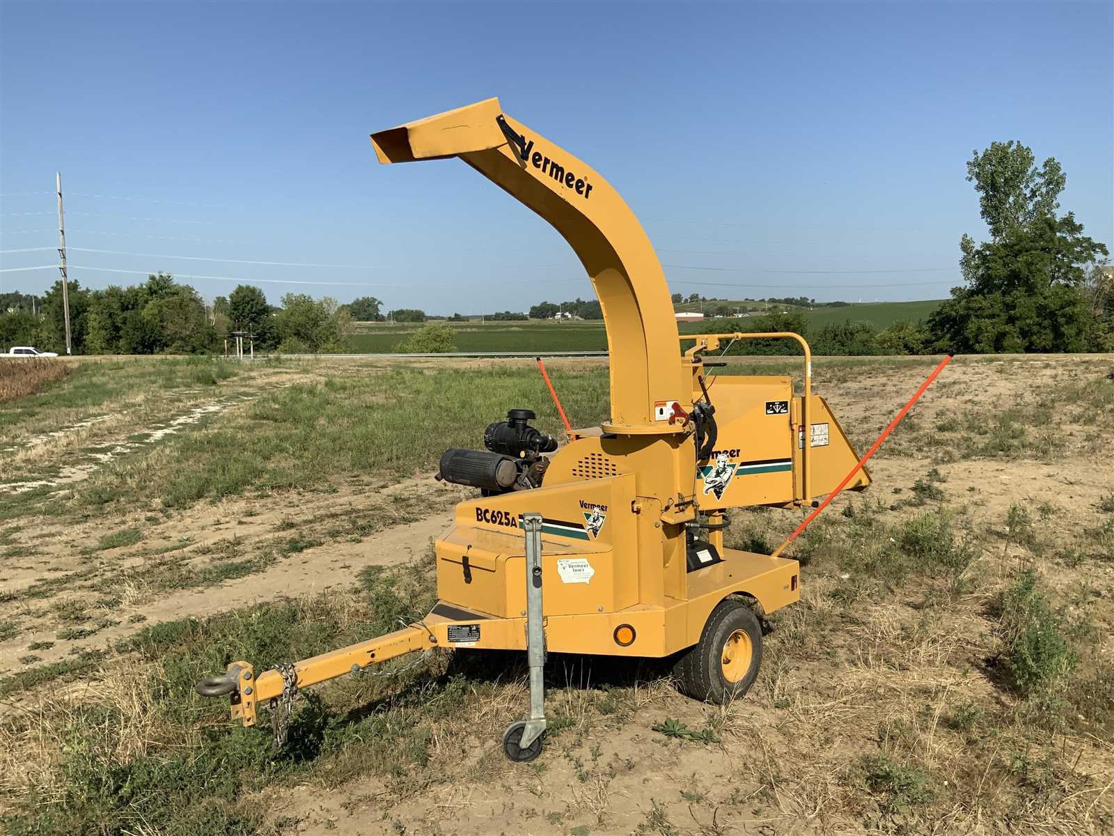
Key Components of the Vermeer BC625A
The structure of this powerful machine is designed with various essential elements that work together to ensure optimal performance. Each component has a specific role, contributing to the efficiency and reliability of the equipment during operation. Understanding these parts is crucial for maintaining and troubleshooting the system.
Engine and Power Unit: At the heart of the device is a robust power unit that drives all other mechanisms. This element provides the necessary energy to keep the machine running smoothly, ensuring consistent output under heavy workloads.
Feeding System: The feeding mechanism plays a key role in handling materials. Its design allows for continuous and efficient intake, minimizing downtime and ensuring the system operates at peak efficiency.
Cutting Mechanism: The cutting system is one of the most critical parts, responsible for processing materials with precision and speed. Its
Understanding the Engine Layout
The engine layout is a crucial component of any mechanical system, providing insight into how power is generated and distributed. By analyzing the structure, one can better understand the relationship between various elements and their functions within the system. Recognizing the arrangement of the engine’s core parts can enhance maintenance and troubleshooting efficiency.
Key components of the layout include the motor itself, cooling mechanisms, and fuel delivery systems, all of which play a role in ensuring optimal performance. Each of these elements is intricately linked, and their placement is designed to maximize efficiency.
Understanding this layout allows operators to identify potential issues early, make necessary adjustments, and ensure that the system runs smoothly. A clear grasp of the arrangement helps reduce downtime and improves the overall functionality of the equipment.
Chipper Blade Assembly Breakdown
The chipper blade is a crucial component in the efficient processing of wood, designed to ensure smooth operation. Understanding its assembly is key to maintaining optimal performance and ensuring safe use. Below is a detailed breakdown of the elements that make up this vital part of the machine.
- Blade: The sharpened component responsible for cutting wood into smaller pieces. It must be periodically inspected for wear and sharpened or replaced as needed.
- Blade Mounting Bolts: These secure the blade in place. Over time, they can loosen and should be checked regularly to prevent malfunction.
- Blade Housing: This enclosure protects the internal mechanisms while supporting the blade. Ensuring it is free of debris is crucial for smooth operation.
- Adjustment Mechanism: Allows fine-tuning of the blade’s position for consistent cuts. Proper alignment is essential for achieving the desired results.
Regular maintenance of these components will not only extend the lifespan of the assembly but also improve the overall efficiency of the machine.
Hydraulic System Parts and Function
The hydraulic system plays a crucial role in powering various mechanisms by utilizing pressurized fluid to transmit force and control movement. This system, made up of several components, works together to ensure smooth operation, enabling efficient and precise control of mechanical actions. In this section, we will explore the key elements that make up the hydraulic system, as well as their individual roles in ensuring seamless functionality.
Main Components of the Hydraulic System
The primary elements responsible for the hydraulic system’s operation include the pump, cylinders, valves, and hoses. These components work together to generate, regulate, and direct hydraulic pressure, providing the necessary force to drive the system’s functions. Each part has a specific role in the movement of the hydraulic fluid, contributing to the system’s overall efficiency.
Functions of Hydraulic Components
Understanding the function of each hydraulic component is essential for maintaining system performance. The pump creates the fluid pressure needed to operate the system
Exploring the Electrical Wiring Diagram
The electrical schematic provides crucial insights into the connectivity and functionality of various components within the machinery. Understanding this layout enables users to troubleshoot issues effectively and optimize the equipment’s performance. Each wire and connection plays a significant role in the operation, making it essential to grasp how they interact.
In examining the schematic, attention should be paid to the different symbols representing electrical elements. These symbols serve as a universal language, facilitating the identification of switches, relays, and power sources. Recognizing these components allows for a more comprehensive understanding of the entire system.
Furthermore, following the pathways indicated in the wiring schematic helps in diagnosing faults. By tracing circuits, users can pinpoint areas of malfunction or wear, thereby enhancing maintenance practices. This proactive approach not only extends the lifespan of the machinery but also ensures safety during operation.
In conclusion, familiarity with the electrical layout is vital for anyone involved in the upkeep or operation of such equipment. A thorough grasp of the connections and their purposes can lead to improved efficiency and reliability, ultimately benefiting the overall functionality of the machinery.
Maintenance Essentials
Regular upkeep is vital for ensuring optimal performance and longevity of your equipment. A well-maintained machine not only operates efficiently but also minimizes the risk of unexpected breakdowns. Understanding key maintenance practices can significantly enhance the functionality of your device.
Begin with routine inspections to identify any wear and tear or potential issues early. Pay close attention to moving parts, as they are often subject to the most stress. Keeping these components clean and lubricated is crucial in preventing premature deterioration.
Scheduled servicing should also be part of your maintenance plan. Adhering to a timeline for checks and repairs helps ensure that all systems are functioning properly. Utilize manufacturer guidelines to determine the appropriate intervals for maintenance tasks.
Documentation of maintenance activities is essential. Keeping a detailed log of inspections, repairs, and replacements allows you to track the history of your equipment and aids in future troubleshooting. This practice not only helps maintain a high performance level but also assists in anticipating future needs.
Common Wear and Tear Parts
In any machinery, certain components are prone to deterioration due to regular use and environmental factors. Understanding these elements is essential for maintaining optimal functionality and preventing unexpected breakdowns. This section outlines the typical items that may require replacement or servicing over time, ensuring longevity and performance.
Frequently Replaced Components
Among the most commonly replaced items are seals and gaskets. These parts are crucial for preventing leaks and maintaining pressure within systems. Over time, exposure to heat and chemicals can lead to their degradation, necessitating periodic checks and replacements.
Signs of Wear
Another vital aspect to monitor is the condition of belts and hoses. These components can suffer from fraying, cracking, or stiffness, indicating the need for immediate attention. Regular inspections can help identify issues early, allowing for timely interventions that can save on costly repairs down the line.
Safety Features and Their Components
Ensuring operational safety is paramount in any machinery. Various mechanisms and devices are integrated to minimize risks and protect users from potential hazards. Understanding these safety features and their individual components is essential for effective operation and maintenance.
Primary Safety Mechanisms
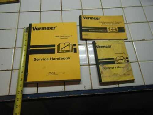
- Emergency Stop Button: A crucial feature that allows for immediate shutdown in emergencies.
- Safety Guards: Physical barriers that prevent access to moving parts, reducing the risk of injury.
- Warning Alarms: Audible signals that alert operators to unsafe conditions or operational issues.
Additional Protective Elements
- Operator Presence Sensors: These sensors ensure that the machinery operates only when the operator is in a safe position.
- Interlock Systems: Mechanisms that prevent the machine from operating under unsafe conditions or configurations.
- Visual Indicators: Lights or displays that provide important information about the operational status and safety alerts.
Replacement Parts for the Vermeer BC625A
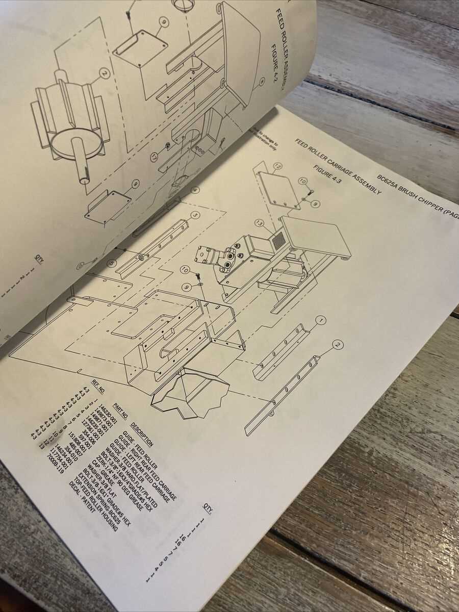
When maintaining and repairing machinery, it’s essential to have access to high-quality components that ensure optimal functionality. Whether you are upgrading or replacing worn-out elements, sourcing reliable substitutes can significantly enhance performance and longevity. This section provides an overview of the various essential components that may require attention during routine maintenance or repairs.
| Component |
Description |
| Blades |
High-strength cutting blades designed for efficient chipping of branches and debris. |
| Belts |
Durable belts that ensure smooth operation and power transmission between moving parts. |
| Hydraulic Hoses |
Robust hoses that withstand high pressure, essential for hydraulic system efficiency. |
| Bearings |
Precision bearings that support rotating elements and reduce friction for enhanced performance. |
| Filters |
High-efficiency filters that keep the engine and hydraulic systems clean, prolonging equipment life. |
How to Read a Parts Diagram Efficiently
Understanding an assembly layout can significantly enhance your ability to identify components and their functions within machinery. This skill is crucial for maintenance and repair tasks, allowing users to streamline their workflow and make informed decisions regarding replacements or repairs.
Here are some effective strategies to help you interpret such layouts:
- Familiarize Yourself with Symbols: Different representations can indicate various parts. Learning the meaning behind these symbols can save you time and reduce confusion.
- Focus on Key Components: Identify and prioritize the main elements. This approach helps you understand the overall structure before diving into smaller details.
- Follow the Flow: Many layouts present components in a logical sequence. Following this progression can assist you in grasping how parts interrelate.
- Utilize Reference Numbers: Cross-referencing numbers can direct you to specific elements and their corresponding descriptions, aiding in clarity.
By employing these techniques, you can enhance your efficiency and accuracy when navigating through technical illustrations, ultimately leading to more successful maintenance and repairs.
