Understanding the individual elements of any mechanical system is crucial for maintaining its performance and ensuring smooth operation. Each component has a specific role in the overall function of the device, and knowing how these parts work together can make a significant difference in both routine maintenance and troubleshooting.
This guide offers an in-depth look at the essential mechanisms and their functions within a specific type of equipment. By breaking down the core elements, we provide valuable insights into how to keep your equipment running efficiently, enhancing both its lifespan and reliability.
Throughout this section, we will delve into the details of various mechanical elements, shedding light on their interaction, purpose, and potential replacement when necessary. This knowledge is fundamental for any user seeking to optimize performance and ensure long-term functionality.
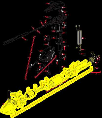
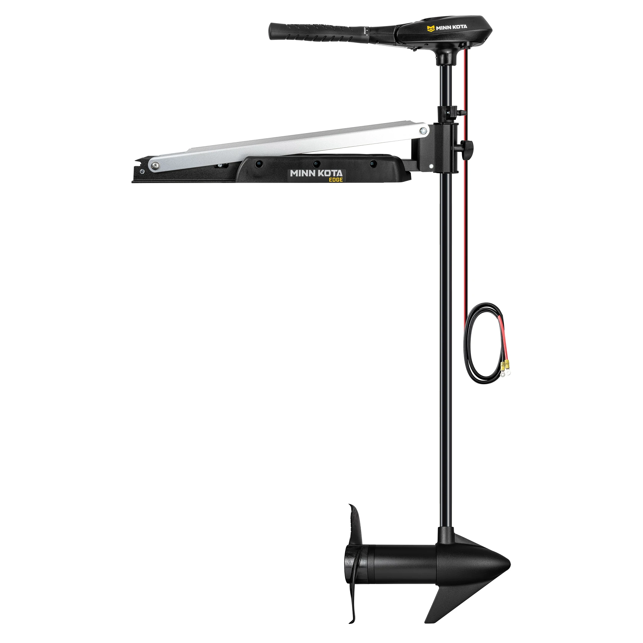
Overview of Minn Kota Edge 45 Components
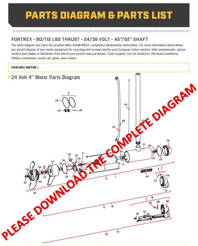
This section provides a comprehensive look at the essential components found in this motor. Understanding each part and how they work together ensures smooth operation and allows for easier maintenance or replacement when necessary. The system is designed to offer durability and reliability in various water conditions.
Main Structure
- Motor Housing – Encases the motor, protecting it from external elements and ensuring optimal performance in different environments.
- Mounting Bracket – This sturdy frame holds the motor securely in place, allowing for easy attachment to your boat.
- Control Head – Contains essential controls, offering simple navigation and operation of the motor while on the water.
Electrical and Mechanical Elements
Main Features of Minn Kota Edge 45
This model of electric motor provides reliable and powerful performance, designed for those who seek efficiency on the water. It combines innovative technology with durability to deliver a smooth and controlled experience during boating. The following features highlight the strengths of this model, making it an ideal choice for both novice and experienced users.
Durability and Strength
Built to withstand harsh marine environments, this motor is constructed with corrosion-resistant materials, ensuring long-lasting performance. Its solid design allows for dependable operation, even in challenging conditions. This makes it a trusted companion for a variety of water-based activities.
Ease of Use and Control
The motor is equipped with intuitive controls, offering a user-friendly experience. With its simple steering mechanism, users can easily maneuver in tight spots or adjust their speed as needed. This ensures maximum control, whether you’re navigating calm waters or dealing with strong currents.
Understanding the Trolling Motor Housing

The external casing of a trolling motor plays a crucial role in protecting its internal components, ensuring smooth operation, and extending the lifespan of the device. It provides a barrier against environmental factors like water and debris, while also maintaining the structural integrity of the motor.
Key Functions of the Motor Housing
- Protection: Shields sensitive parts from moisture, dirt, and damage.
- Durability: Built from materials designed to withstand harsh conditions, ensuring long-term use.
- Heat Dissipation: Helps prevent overheating by promoting efficient cooling.
Common Materials Used
Different types of materials are used to construct these casings, depending on the specific model and the operating environment. Most common options include:
- Aluminum: Lightweight and corrosion-resistant, ideal for freshwater conditions.
- Detailed Look at the Motor Shaft
The motor shaft plays a crucial role in the overall performance of the propulsion system. This component serves as the connection between the motor and the propeller, transferring energy efficiently to ensure smooth movement. Understanding its structure and function can provide valuable insights into how the entire system operates.
Key Components of the Shaft
The shaft is designed to withstand both pressure and corrosion, typically made from durable materials like stainless steel. This ensures longevity and resistance to the elements, particularly in marine environments. The length and thickness of the shaft are critical factors, impacting both stability and performance.
Maintenance and Care
Regular inspection of the shaft is essential for ensuring optimal performance. Over time, debris or corrosion can affect its functionality. Routine cleaning and lubrication can prevent wear and tear, extending the life of the component and maintaining efficiency in the system.
Control Board and Circuitry Layout
The control board is a critical component responsible for managing electrical signals and regulating the overall functionality of the motor system. It ensures that the power flows correctly between the various parts, maintaining the proper operation of the device. Understanding how the control board is organized and how the circuits are laid out is essential for effective troubleshooting and maintenance.
Key areas of focus include the arrangement of essential connections, the placement of relays, and the interaction of various circuit elements. These elements must be properly aligned to ensure a smooth and efficient performance. Incorrect wiring or
Foot Pedal Wiring and Functionality
The foot control mechanism serves as a crucial component for operating various aquatic propulsion systems. It enables users to manage speed and direction seamlessly, enhancing the overall experience on the water.
Understanding the electrical connections within this control unit is essential for effective maintenance and troubleshooting. The wiring typically consists of multiple color-coded wires, each corresponding to specific functions such as acceleration, deceleration, and directional control. Proper wiring ensures that signals are transmitted efficiently, allowing for responsive maneuvering.
Functionality of the foot pedal is primarily determined by its internal circuitry, which interprets the user’s input and converts it into actionable commands for the motor. The pedal’s design allows for smooth operation, enabling precise adjustments while navigating various water conditions.
Regular inspections of the wiring and connections can help identify potential issues before they escalate. Ensuring that all components are securely attached and free from corrosion is vital for maintaining reliable performance.
Propeller Assembly Breakdown
The propeller assembly is a crucial component of any motorized vessel, playing a significant role in its propulsion system. Understanding the various elements that make up this assembly can help users maintain their equipment effectively and ensure optimal performance on the water. In this section, we will explore the main parts that contribute to the overall functionality of the propeller assembly.
Key Components
The assembly consists of several key components, each serving a specific purpose. The propeller blades are designed to create thrust, allowing the vessel to move forward efficiently. The hub connects the blades to the motor shaft, transferring power effectively. Additionally, hardware such as nuts and bolts secure the assembly, ensuring stability during operation.
Maintenance Considerations
Regular maintenance of the propeller assembly is essential for longevity and performance. Inspecting the blades for damage or wear is critical, as any irregularities can affect efficiency. Furthermore, checking the hub for tightness and replacing any corroded hardware can prevent failures during use. By understanding these elements, users can keep their systems in top condition.
Battery Connection and Wiring Guide
Connecting and wiring batteries properly is crucial for ensuring optimal performance and longevity of your equipment. This section provides essential insights into the procedures and considerations necessary for effective power management. Understanding the correct setup will help prevent potential issues and enhance the efficiency of your device.
Begin by identifying the battery type suitable for your system, as different configurations may require specific connectors and cables. It is important to ensure that the voltage ratings match and that the terminals are clean and free from corrosion. Use the appropriate gauge of wiring to handle the current demands, which will minimize resistance and heat buildup.
When connecting the battery, always start with the positive terminal, followed by the negative. This practice helps prevent short circuits during the connection process. For added safety, consider using circuit breakers or fuses in the wiring setup to protect against overloads. Regularly inspect connections to ensure they remain secure and functional over time.
By following these guidelines, you can create a reliable and efficient power source that meets the needs of your equipment, ultimately leading to a smoother operational experience.
Mounting Bracket and Support Parts
The mounting bracket and support components are essential for ensuring stability and functionality in various systems. These elements provide the necessary foundation for proper operation, allowing for secure installation and effective performance.
Key Components
- Brackets: These are designed to hold the unit securely in place, preventing movement during operation.
- Support Arms: These extend from the brackets, offering additional stability and load distribution.
- Fasteners: Essential for securing the brackets and support components to the main structure, ensuring everything remains firmly attached.
Installation Considerations
- Ensure all components are compatible with the intended application.
- Use the appropriate tools for installation to avoid damage to parts.
- Regularly check the integrity of the mounting system to maintain safety and functionality.
Steering System and Cable Design
The steering mechanism plays a crucial role in ensuring smooth navigation and control of a watercraft. The effectiveness of this system is largely determined by its construction and the quality of the components used, which work together to provide precision and reliability during operation.
Typically, the steering setup comprises a series of cables that transmit the movement of the steering wheel to the rudder or motor, facilitating responsive maneuvering. A well-designed cable system minimizes friction and enhances sensitivity, allowing for more effortless adjustments while on the water.
Component Description Function Steering Wheel Primary control interface for the operator Transmits user input to the steering system Cable Assembly Flexible conduit connecting the wheel to the rudder Transfers motion from the steering wheel to the rudder Rudder Control surface at the rear of the vessel Steers the boat by redirecting water flow Pulleys Mechanical components that guide cables Reduce friction and allow for smooth cable movement Mounting Bracket Support structure for cable components Secures the assembly in place for stability Understanding the various elements of the steering configuration is essential for maintenance and upgrades. Regular inspection of the cables and associated components can prevent wear and ensure that the system operates at optimal performance levels.
How to Replace Common Motor Parts
Replacing components of a motor can enhance its performance and prolong its lifespan. Understanding the replacement process is essential for effective maintenance, ensuring your equipment operates smoothly. Here are some common components you might need to replace and the steps involved in doing so.
- Propeller:
- Disconnect the power source to prevent any accidents.
- Remove the cotter pin securing the propeller.
- Unscrew the propeller from the shaft.
- Attach the new propeller and secure it with the cotter pin.
- Throttle Control:
- Turn off the motor and disconnect the battery.
- Locate the throttle assembly and remove any screws or bolts holding it in place.
- Disconnect the wiring harness from the old control.
- Install the new throttle control and reconnect the wiring.
- Secure it with screws or bolts.
- Electrical Connections:
- Ensure the motor is powered off.
- Inspect the connections for wear or damage.
- Disconnect the damaged wires carefully.
- Strip the ends of the new wires and connect them using suitable connectors.
- Insulate the connections with electrical tape.
- Battery:
- Turn off the motor and remove any covers to access the battery compartment.
- Disconnect the negative terminal first, followed by the positive terminal.
- Remove the old battery and replace it with a new one, ensuring the correct orientation.
- Reconnect the positive terminal first, then the negative terminal.
By following these steps, you can effectively replace essential components of your motor, ensuring it remains in optimal working condition.
Troubleshooting Electrical Connections
Ensuring proper functionality of electrical systems is crucial for optimal performance. This section aims to guide users through common issues related to electrical links in devices. Identifying problems in wiring, connectors, and terminals can prevent malfunctions and enhance reliability.
Identifying Common Issues
Frequent symptoms of electrical issues include intermittent operation, complete failure, or unexpected behavior. Begin by inspecting all visible connections for signs of corrosion, fraying, or loose fittings. A thorough visual assessment can reveal underlying problems that might not be immediately apparent.
Testing and Repairing Connections

To effectively diagnose electrical issues, utilize a multimeter to check voltage levels and continuity. If discrepancies are found, consider tightening connections or replacing faulty components. Regular maintenance of electrical systems ensures longevity and efficient operation.
Maintenance Tips for Motor Longevity
Ensuring the durability of your propulsion device requires consistent care and attention. Regular maintenance not only enhances performance but also prolongs the lifespan of your equipment. Here are some essential strategies to keep your motor operating smoothly for years to come.
Regular Cleaning
Keeping the exterior and interior of your motor clean is crucial. Debris, saltwater, and other contaminants can cause damage over time. Follow these steps for effective cleaning:
- Rinse the motor with fresh water after each use, especially if used in saltwater.
- Use a soft brush to remove dirt and grime.
- Inspect and clean electrical connections to prevent corrosion.
Routine Inspections
Conducting routine inspections can help identify potential issues before they escalate. Pay attention to the following:
- Check for wear and tear on the propeller and shaft.
- Examine wiring for signs of damage or fraying.
- Monitor fluid levels and ensure they are within recommended limits.
Implementing these maintenance practices will significantly contribute to the longevity and efficiency of your motor, allowing for a more enjoyable experience on the water.