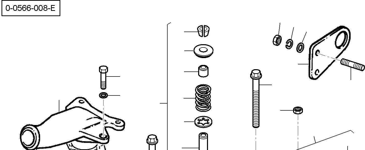
Understanding the structure and layout of machinery is crucial for ensuring efficient operation and smooth maintenance. By examining the individual elements that make up the system, users can gain insights into the role each component plays in the overall functionality. This knowledge aids in troubleshooting and replacement tasks, making the entire process more manageable.
Each section focuses on specific mechanical segments, helping users identify essential items and their relationships within the system. Highlighting these crucial areas provides a clearer understanding of how everything fits together, allowing for better long-term care and upkeep of the equipment.
Recognizing the intricate arrangement of various elements ensures that repairs and replacements are done with precision, minimizing downtime. Whether dealing with minor issues or major overhauls, a thorough understanding of the layout is invaluable for maintaining optimal performance.
Engine Components Overview
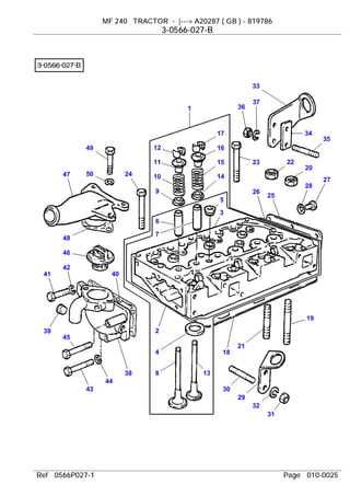
The internal combustion mechanism consists of various crucial elements working together to ensure smooth operation. This section provides an overview of the main parts that are essential for the functionality of the power unit.
Key Elements of the Power Unit
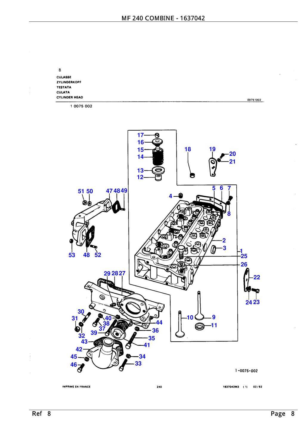
- Cylinders: These are the chambers where fuel combustion occurs, generating power.
- Pistons: Located within the cylinders, they transfer the force from combustion to the crankshaft.
- Crankshaft: This rotating component converts the pistons’ linear motion into rotational energy.
- Valves: Responsible for controlling the intake of air and fuel, as well as the exhaust of gases after combustion.
- Camshaft: Coordinates the timing of the valve operations, ensuring precise fuel intake and exhaust release.
Supporting Systems
Additional systems surrounding the core components play a vital ro
Transmission System Parts and Functions
The transmission system plays a crucial role in managing the power transfer from the engine to the wheels. It ensures that the vehicle operates efficiently by adjusting torque and speed ratios. This section will explain the components involved and how they work together to facilitate smooth gear shifting and motion control.
Main Components of the Transmission
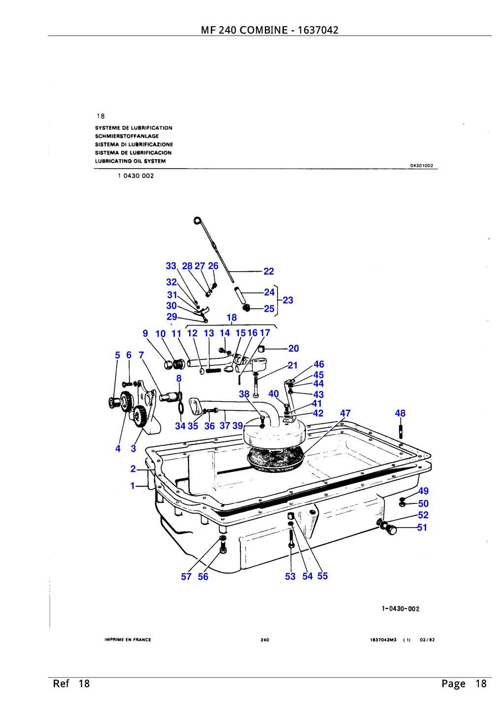
- Clutch Assembly: This component engages and disengages power flow from the engine to the gearbox, allowing for gear changes and control over power delivery.
- Gearbox: Houses the gears that manage torque and speed conversion. It enables the adjustment of gear ratios to match different driving conditions.
- Driveshaft: Transfers power from the gearbox to the differential, which is responsible for distributing torque to the wheels.
- Synchronizers: Ensure that gears mesh smoothly by matching the speed of different gears during shifts, minimizing wear and enhancing performance.
Functionality in Various Driving Conditions
- Low-Speed Operations: T
Hydraulic System Elements and Their Role

The hydraulic system plays a crucial role in ensuring smooth operation by transferring force through fluid pressure. This mechanism involves several essential components that work together to control and distribute power efficiently. Each element has its specific function, contributing to the overall performance of the system.
- Pump: Responsible for generating the necessary fluid pressure to activate other components.
- Valves: Regulate fluid flow, controlling the direction and pressure in different parts of the system.
- Cylinders: Convert fluid power into mechanical motion, allowing movement of various parts.
- Filters: Ensure the cleanliness of hydraulic fluid, preventing contamination that could harm the system.
- Reservoir
Electrical System Parts and Connections
In this section, we will explore the key components and their wiring connections within the vehicle’s electrical framework. Understanding how these elements work together is crucial for maintaining and repairing the system, ensuring smooth operation and preventing potential malfunctions.
Key Components of the Electrical Circuit
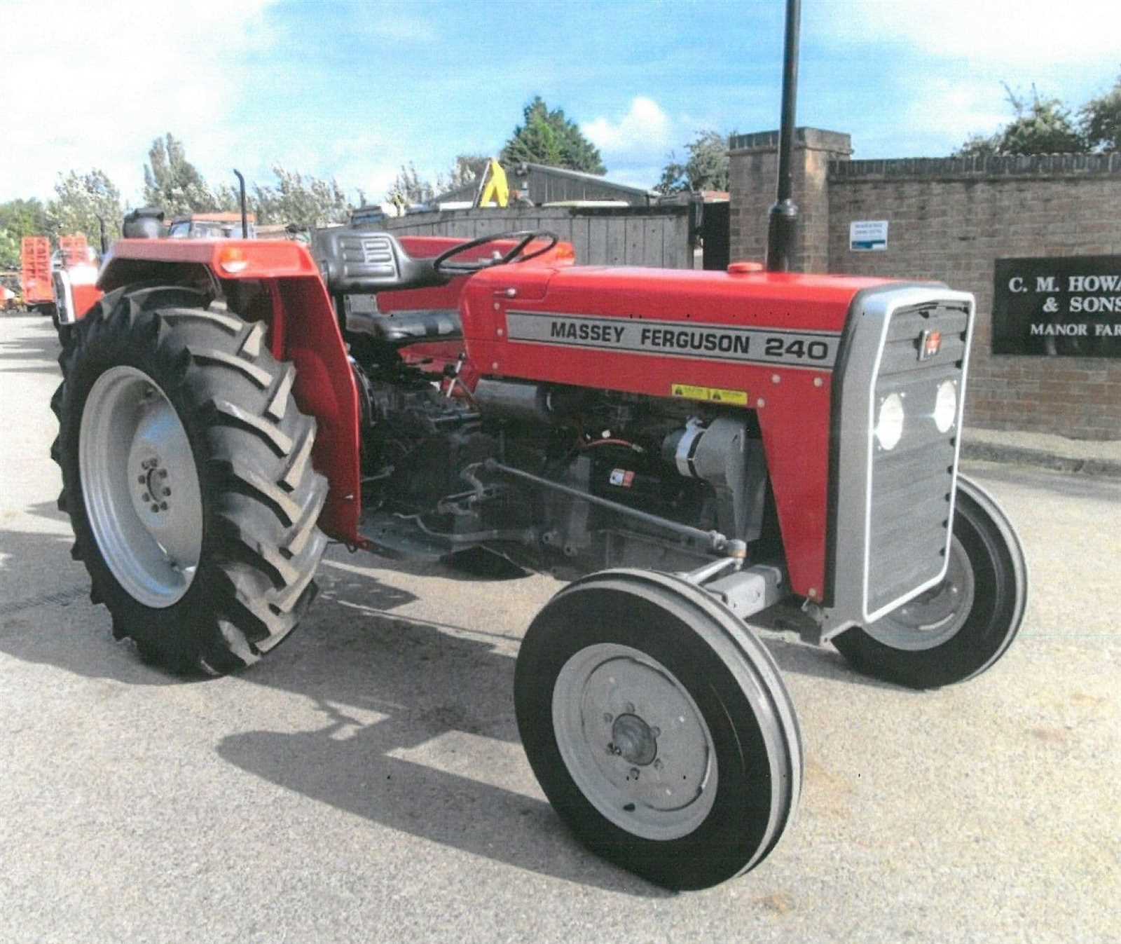
The system primarily consists of essential units like the power source, distribution network, and several control modules. These units are interconnected, providing energy to lights, sensors, and various functional devices. Each connection must be secure to avoid issues related to performance.
Connection Diagram and Terminals
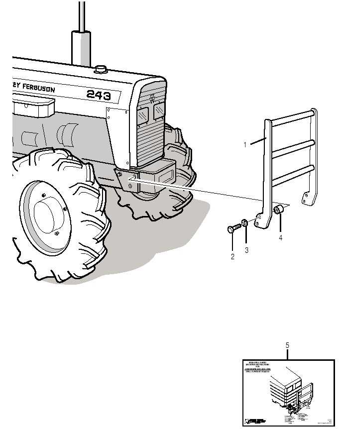
Below is a simplified table that shows some of the important connections involved in this electrical network, along with their respective terminal points:
Component Terminal Function Battery Positive (+) Provides power to the entire system Steering Mechanism Components and Usage
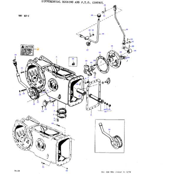
The steering system is a critical part of any vehicle’s operation, enabling the driver to control direction smoothly and effectively. Understanding how the main elements interact is key to maintaining precise control on the road.
The steering wheel serves as the primary interface, transferring the driver’s input to other mechanical components. It connects to the steering shaft, which converts the rotational motion into a form usable by the system. The steering box or gear works to amplify and refine this motion, ensuring the driver can easily maneuver the vehicle with minimal effort.
Connecting these components to the wheels, the linkage system plays a pivotal role. It consists of rods and joints that transmit the movement from the steering box to the wheels, enabling them to turn left
Fuel System Layout and Parts Guide
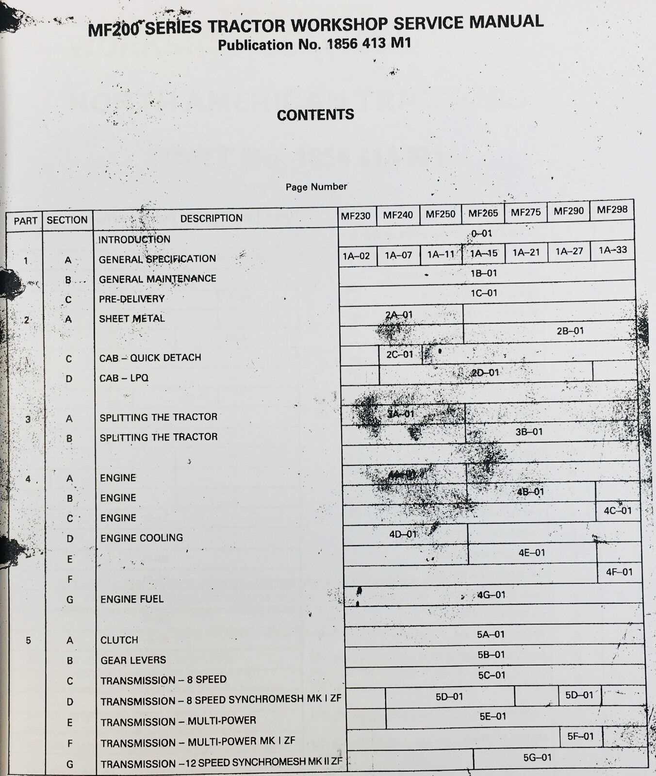
The fuel system of an agricultural vehicle plays a crucial role in ensuring efficient operation and performance. This section provides an overview of the components involved in the fuel delivery process, outlining their functions and interconnections.
Component Description Fuel Tank Stores fuel for the engine, providing a reservoir for optimal supply. Fuel Pump Moves fuel from the tank to the engine at the required pressure. Fuel Filter Removes impurities from the fuel to protect the engine and enhance performance. Fuel Injector Delivers the precise amount of fuel into the combustion chamber for efficient combustion. Fuel Lines Transport fuel between the tank, pump, filter, and engine. Cooling System Parts Identification
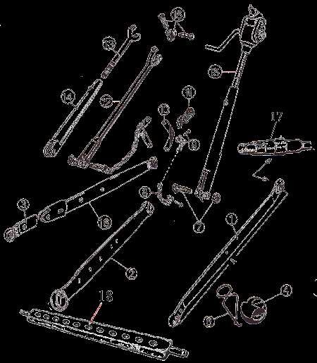
The cooling mechanism of agricultural machinery is crucial for maintaining optimal operating temperatures. Understanding the various components involved in this system allows for efficient troubleshooting and maintenance, ensuring reliable performance during operations.
Main Components of the Cooling Mechanism
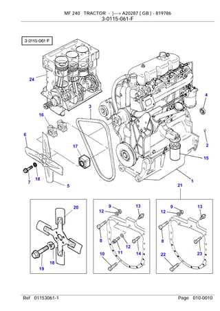
- Radiator: Facilitates heat exchange, cooling the coolant fluid.
- Water Pump: Circulates coolant throughout the engine and radiator.
- Thermostat: Regulates the flow of coolant based on temperature.
- Hoses: Transport coolant between components.
- Cooling Fan: Assists in airflow to enhance cooling efficiency.
Signs of Cooling System Issues
- Overheating engine: Indicates insufficient coolant flow or cooling.
- Coolant leaks: Suggests damaged hoses or fittings.
- Unusual noises: May indicate failing water pump or loose components.
- Dashboard warning lights: Alerts to potential overheating or low coolant levels.
Brake System Components and Operation

The braking mechanism is a vital aspect of any vehicle’s functionality, ensuring safety and control during operation. Understanding its elements and how they work together is essential for effective maintenance and performance.
- Brake Pedal: The driver’s primary interface, allowing the application of braking force.
- Master Cylinder: Converts the mechanical force from the pedal into hydraulic pressure.
- Brake Lines: Tubes that transfer hydraulic fluid from the master cylinder to the brake components.
- Brake Calipers: Clamps that hold the brake pads against the rotors to create friction.
- Brake Pads: Friction material that presses against the rotor to slow down the wheels.
- Brake Rotors: Discs that rotate with the wheels, providing a surface for the brake pads to grip.
- Parking Brake: A separate mechanism that secures the vehicle when stationary.
Each component plays a critical role in the overall functionality of the braking system. When the pedal is pressed, the master cylinder generates hydraulic pressure that travels through the brake lines, activating the calipers and causing the brake pads to engage with the rotors. This process effectively slows down or stops the vehicle.
Front Axle Components and Assembly
The front axle assembly plays a crucial role in ensuring stability and maneuverability in agricultural machinery. It is composed of various elements that work together to support the weight of the vehicle and facilitate smooth movement across different terrains.
Key Elements: The main components include the axle housing, steering knuckles, spindles, and wheel hubs. Each part is designed to withstand the stresses encountered during operation, contributing to the overall efficiency of the equipment.
Assembly Process: Proper assembly is vital for optimal performance. The components must be aligned accurately, and fasteners tightened to the specified torque. Regular maintenance checks can help identify wear and ensure longevity.
Rear Axle Components and Maintenance
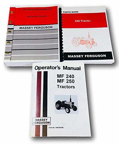
The rear axle plays a crucial role in the functionality and stability of agricultural machinery. Regular inspection and proper upkeep are essential to ensure optimal performance and longevity.
Key components of the rear axle include:
- Housing: Encloses the internal components, providing protection and support.
- Bearings: Allow smooth rotation of the axle while supporting the weight of the vehicle.
- Drive Shaft: Transmits power from the engine to the wheels.
- Differential: Distributes torque to the wheels, allowing them to rotate at different speeds during turns.
- Brake Assembly: Responsible for stopping the vehicle safely.
To maintain the rear axle effectively, consider the following practices:
- Regularly inspect for leaks and signs of wear.
- Ensure proper lubrication of bearings and moving parts.
- Check the alignment of the axle to avoid undue stress.
- Monitor brake functionality and replace worn components as needed.
- Consult the manufacturer’s guidelines for specific maintenance intervals.
Cab and Control Panel Parts Diagram
This section provides an overview of the essential components found within the operator’s cabin and control interface of the vehicle. Understanding these elements is crucial for effective operation and maintenance.
Key Components
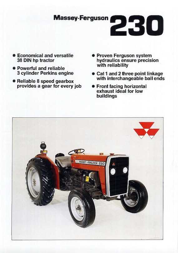
- Steering Wheel
- Dashboard
- Control Levers
- Instrument Cluster
- Switches and Buttons
Functionality Overview
The various elements of the control panel serve multiple purposes:
- The steering wheel allows for maneuverability.
- The dashboard displays critical information such as speed and fuel levels.
- Control levers operate different functions of the machine.
- The instrument cluster provides warnings and system statuses.
- Switches and buttons control auxiliary features and settings.