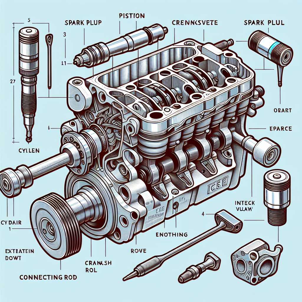
The intricate workings of mechanical systems are a marvel of engineering, showcasing a harmonious blend of various elements that contribute to overall functionality. Each component plays a critical role, and comprehending their interrelations is essential for grasping how these systems operate efficiently. The complexity of these assemblies can be daunting, yet a closer examination reveals a structured organization that underpins their performance.
In this exploration, we will delve into the essential building blocks that drive motion and power transfer. By dissecting these elements, one gains insight into their specific functions and how they interact within the broader context of machinery. This understanding not only enhances technical knowledge but also fosters appreciation for the sophistication inherent in mechanical design.
As we navigate through the various elements, it becomes clear that each one is engineered with precision, designed to withstand the stresses of operation while maintaining optimal efficiency. Recognizing the significance of these components allows for better maintenance practices and informed decisions when it comes to troubleshooting and repairs.
Understanding Engine Components
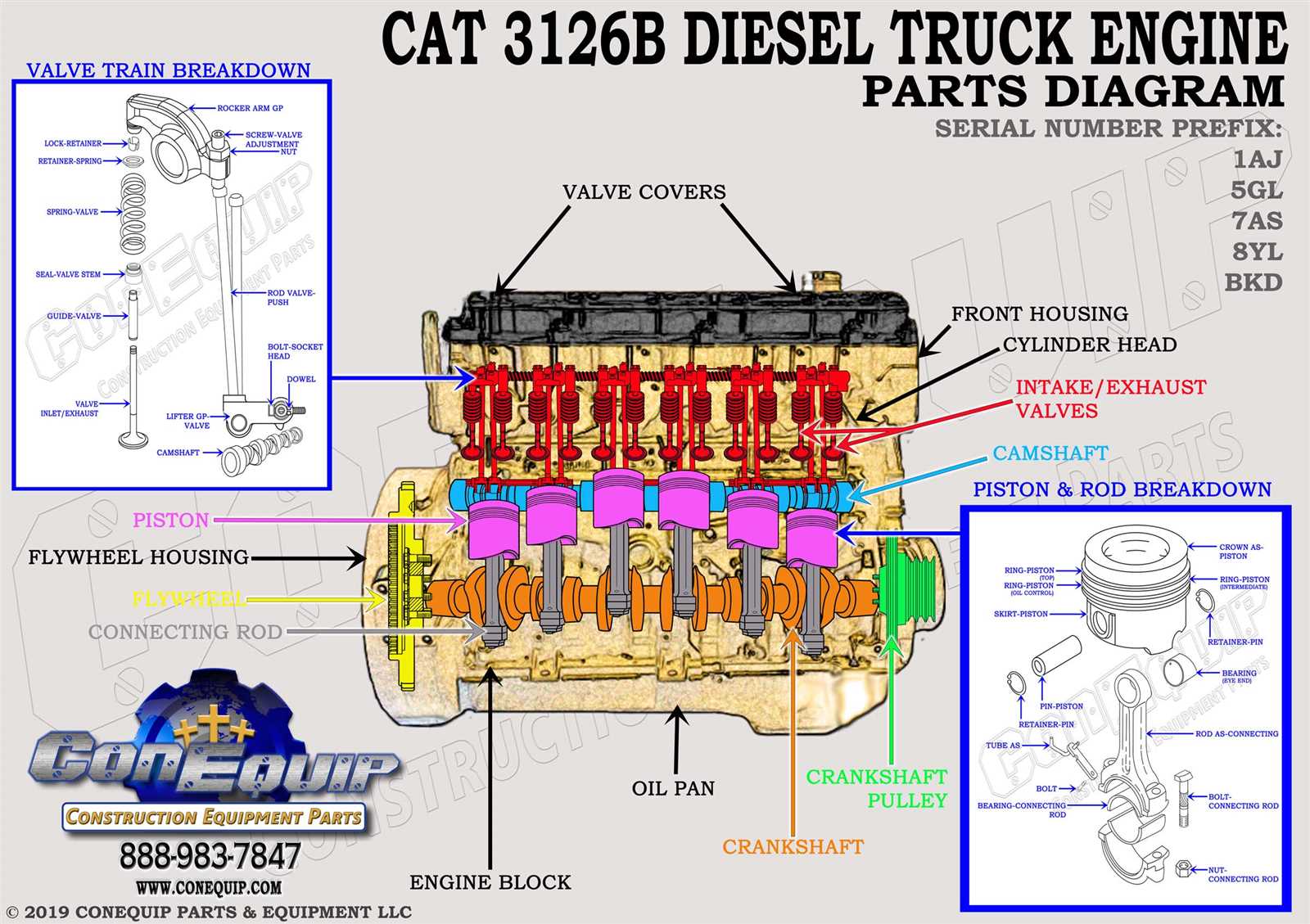
The intricate assembly of a mechanical system relies on various essential elements that work in harmony to produce movement and power. Each component plays a vital role, contributing to the overall functionality and efficiency of the unit. A comprehensive understanding of these elements is crucial for both enthusiasts and professionals in the field.
First and foremost, there are elements that manage the conversion of fuel into energy. These include components designed to initiate combustion, regulate airflow, and ensure optimal performance. The efficiency of this process directly impacts the power output and fuel consumption.
Additionally, the structural integrity of the assembly is maintained through supportive elements that absorb stress and withstand high temperatures. These components are engineered to endure harsh conditions while facilitating smooth operation.
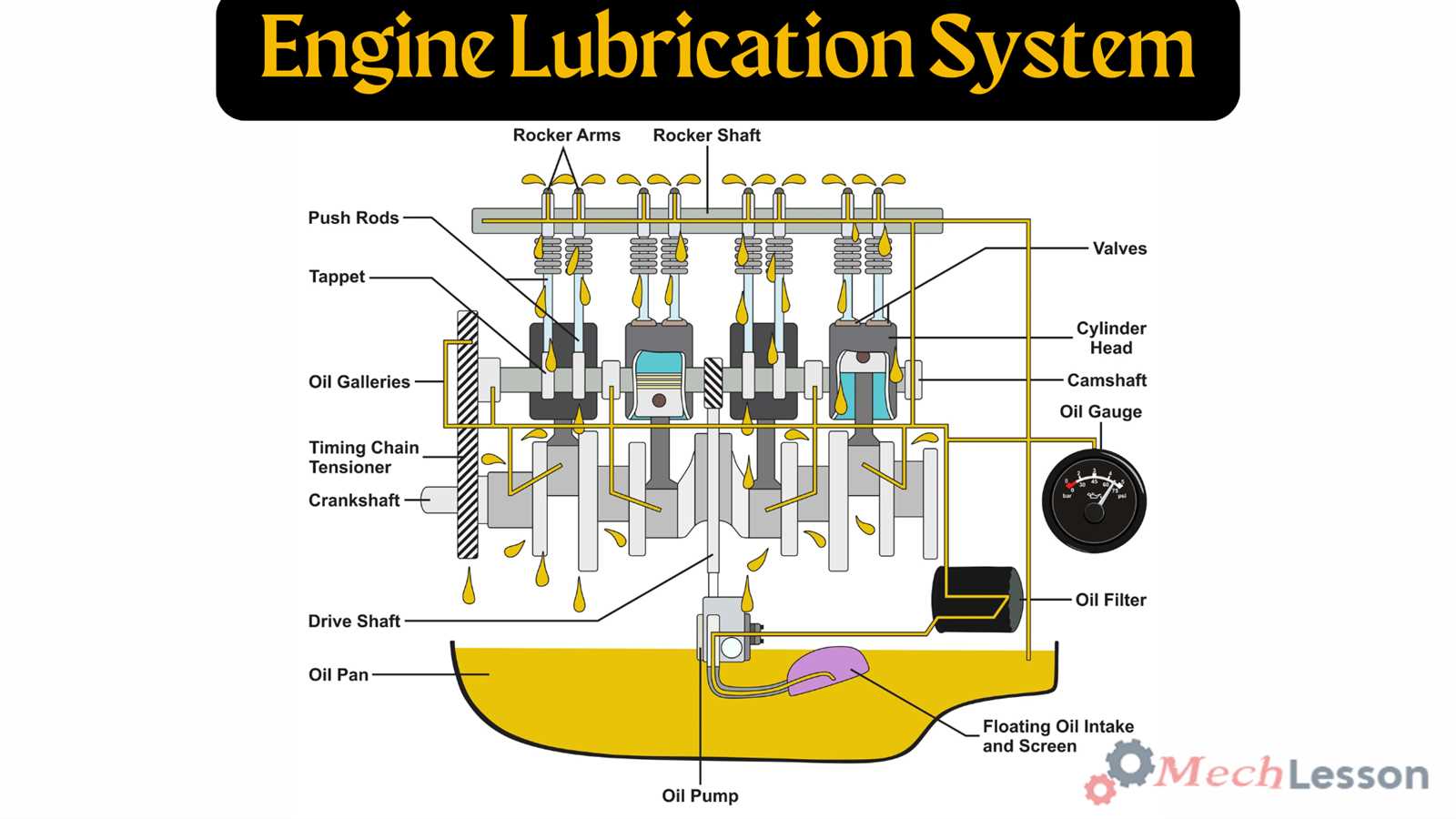
Moreover, various systems within the structure work to enhance performance through lubrication, cooling, and exhaust management. Each of these functions is critical in preventing damage and ensuring longevity.
In summary, grasping the roles and interactions of these fundamental elements is essential for anyone seeking to appreciate the complexity and innovation inherent in mechanical systems.
Overview of Engine Diagrams
Visual representations play a crucial role in understanding complex machinery. They offer insights into the arrangement and function of various components, allowing for a clearer grasp of how systems interact and operate effectively.
These illustrations serve multiple purposes, including:
- Facilitating learning and education.
- Assisting in maintenance and troubleshooting.
- Enhancing communication among professionals.
Key elements typically featured in these visuals include:
- Structural layouts showcasing component placements.
- Flow paths illustrating movement and energy transfer.
- Labeling systems for easy identification of features.
Overall, such representations are invaluable tools for anyone involved in the study or maintenance of machinery, allowing for a deeper understanding of how each segment contributes to the overall functionality.
Key Parts Explained
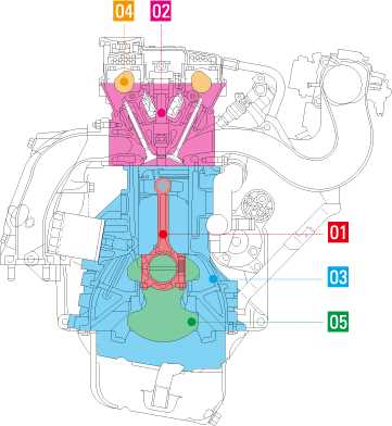
This section aims to illuminate the fundamental components that play a crucial role in the functioning of mechanical systems. Understanding these elements is essential for grasping how they work together to produce power and efficiency.
Core Elements
The primary elements serve as the backbone, enabling various processes to occur seamlessly. These components interact harmoniously, ensuring optimal performance and reliability in operation.
Supporting Mechanisms
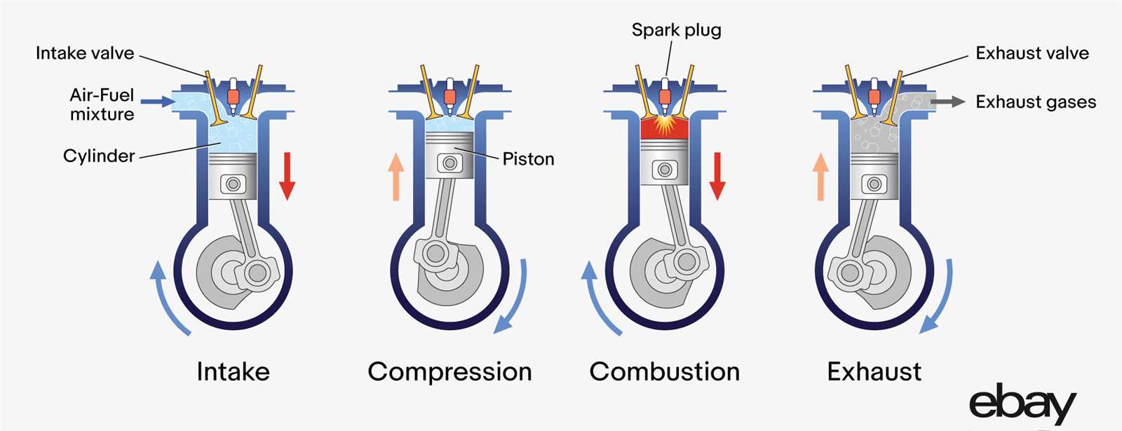
In addition to the core elements, supporting mechanisms are vital for enhancing efficiency and stability. These auxiliary parts contribute to the overall functionality, allowing for smooth transitions and reduced wear over time.
Function of the Crankshaft
The crankshaft plays a pivotal role in the transformation of linear motion into rotational energy. It serves as a crucial component that enables the smooth operation of various mechanisms within a power-generating system. By connecting with other elements, it ensures that kinetic energy is efficiently harnessed and utilized.
This vital shaft converts the up-and-down motion of pistons into a circular movement, allowing for the continuous rotation necessary for propulsion. Its design incorporates counterweights to balance the forces acting upon it, reducing vibrations and enhancing overall performance. Through this process, the crankshaft maintains stability and efficiency, contributing significantly to the power output.
Additionally, the crankshaft often plays a role in synchronizing other moving parts, ensuring that operations remain coordinated. This synchronization is essential for optimal functionality, influencing aspects such as timing and power delivery. In summary, the crankshaft is integral to the seamless operation of the entire system, facilitating the conversion of energy while maintaining balance and efficiency.
The Role of Pistons
Pistons play a crucial part in the functionality of internal combustion systems, transforming energy from fuel into mechanical power. This process is vital for the overall performance and efficiency of the machinery.
Key functions of pistons include:
- Creating compression in the combustion chamber
- Transmitting force to the crankshaft
- Facilitating the intake and exhaust cycles
The interaction of pistons with other components ensures smooth operation and effective power generation. Their design and materials significantly influence durability and performance.
- Material selection affects heat resistance.
- Shape impacts aerodynamics within the chamber.
- Weight influences overall efficiency.
Ultimately, the efficiency and reliability of mechanical systems rely heavily on the functionality of pistons, underscoring their importance in modern technology.
Importance of Valves
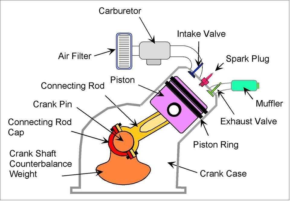
Valves play a crucial role in regulating the flow of various substances within a mechanical system. Their function ensures that processes occur efficiently and at the right moments, directly impacting performance and overall reliability.
Effective control is one of the primary benefits of valves. They manage the entry and exit of fluids and gases, allowing for precise timing and coordination. This regulation is essential for maintaining optimal operation.
Moreover, valves contribute to the overall safety of the system. By preventing backflow and controlling pressure, they minimize the risk of failures and potential hazards. Their reliability is vital for the longevity of mechanical components.
In conclusion, the significance of valves cannot be overstated. Their ability to manage flow and enhance safety underscores their ultimate importance in any mechanical arrangement.
How the Camshaft Works
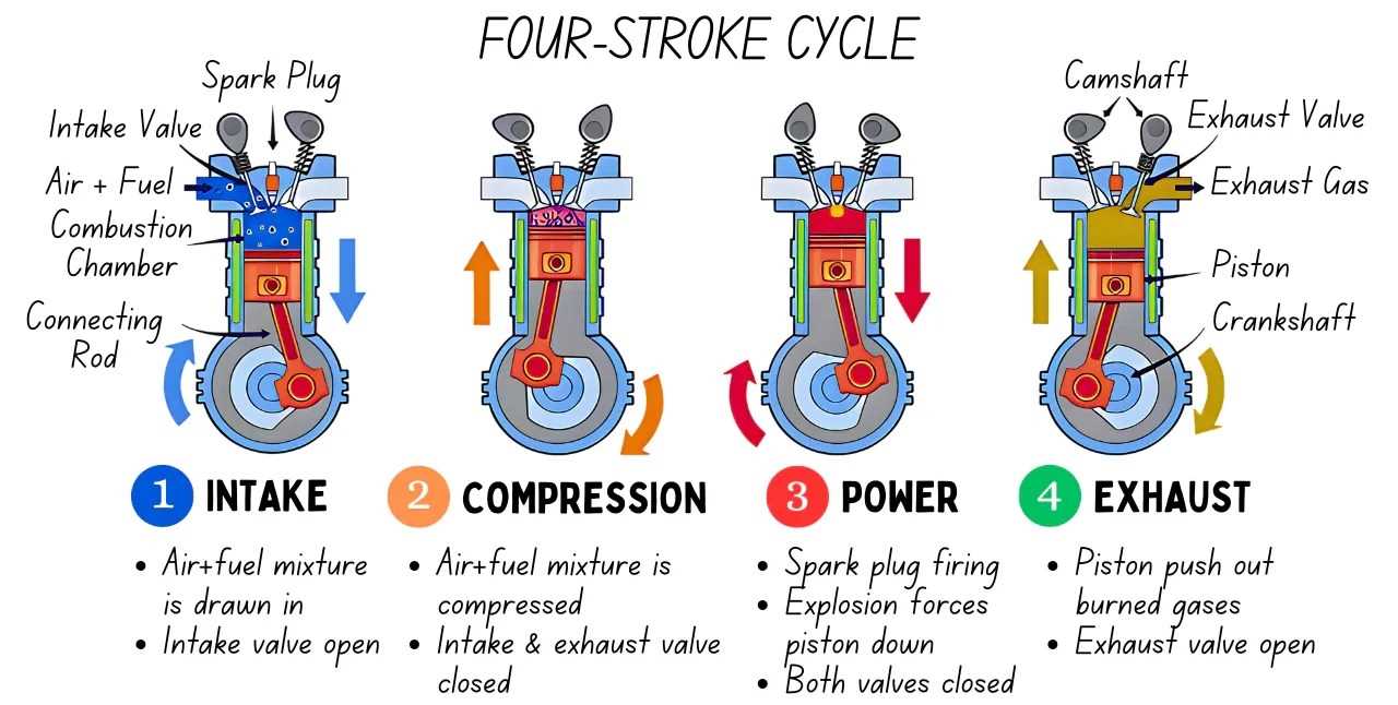
The camshaft plays a pivotal role in regulating the timing of various mechanical movements within the machinery. Its primary function is to convert rotational motion into linear movement, allowing components to open and close in a precise sequence. This synchronization is crucial for optimal performance and efficiency.
As the camshaft rotates, its uniquely shaped lobes push against followers or lifters, causing them to move up and down. This action controls the opening and closing of valves, which is essential for the intake of air and the expulsion of exhaust gases. The design of the lobes determines the timing and duration of each valve’s operation, influencing the overall functionality of the system.
| Feature | Description |
|---|---|
| Rotation | Transforms rotational motion into linear motion. |
| Lobe Design | Shapes that dictate timing and valve operation. |
| Followers | Components that respond to the lobes’ movement. |
| Synchronization | Ensures proper sequence of movements for efficiency. |
Understanding the function of the camshaft is essential for grasping how the various elements within the machinery interact to produce power. Its design and operation significantly affect performance, efficiency, and responsiveness, making it a critical component in the overall system.
Significance of the Cylinder Head
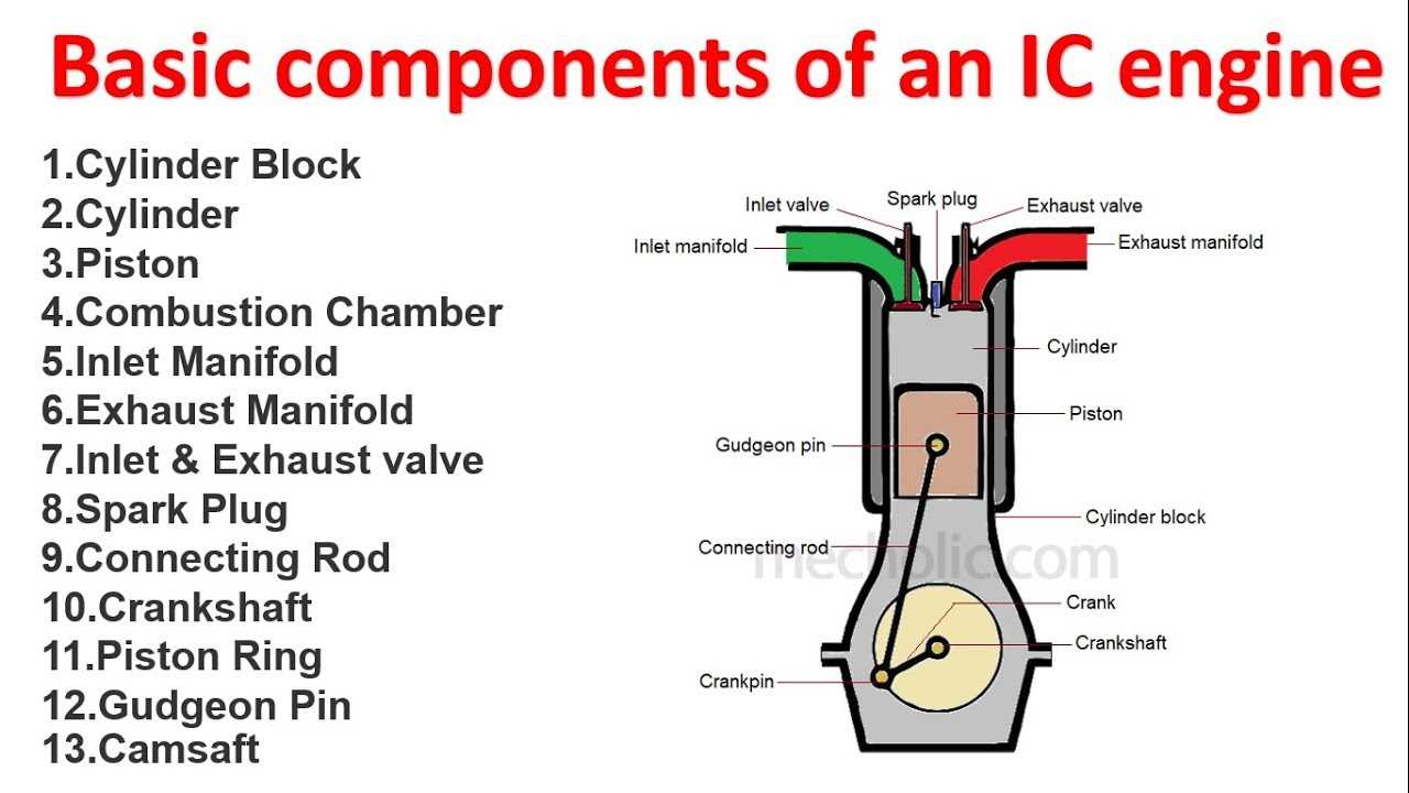
The cylinder head plays a crucial role in the overall functionality and performance of a combustion mechanism. It acts as a vital interface, facilitating the complex interactions between various components while ensuring optimal efficiency and power generation.
One of the primary functions of the cylinder head is to seal the combustion chamber, maintaining the necessary pressure for effective fuel ignition. This sealing not only prevents the escape of gases but also enhances the compression ratio, which is essential for maximizing output and minimizing fuel consumption.
Moreover, the design of the cylinder head influences airflow within the chamber, significantly impacting combustion quality. An optimized airflow pattern allows for better mixing of air and fuel, resulting in a more complete burn and reduced emissions. This optimization is critical for meeting environmental standards and improving overall performance.
In addition, the cylinder head houses crucial components such as valves and spark plugs. The positioning and operation of these elements directly affect timing and efficiency, underscoring the importance of precise engineering in this area. A well-designed head contributes to smoother operation and longevity of the entire system.
Ultimately, the significance of the cylinder head cannot be overstated; it serves as a pivotal element that integrates various functions, enhancing the performance and reliability of the machinery as a whole.
Fuel Injection Systems Explained
Fuel injection systems are crucial for optimizing the combustion process in modern vehicles. These sophisticated mechanisms precisely deliver fuel to the combustion chamber, enhancing efficiency and performance. By controlling the amount of fuel injected based on various factors, they significantly impact power output and emissions.
How Fuel Injection Works
At the core of a fuel injection system is the objective to ensure that the right quantity of fuel is mixed with air before combustion. This process involves several key elements:
- Fuel Pump: Moves fuel from the tank to the injection system.
- Fuel Injector: Atomizes the fuel and sprays it into the combustion chamber.
- Electronic Control Unit (ECU): Manages fuel delivery based on sensor inputs.
- Pressure Regulator: Maintains consistent fuel pressure for optimal performance.
Types of Fuel Injection Systems
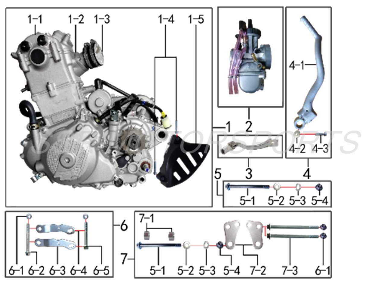
There are various types of fuel injection systems, each with unique characteristics and advantages:
- Sequential Fuel Injection: Injects fuel into each cylinder individually, optimizing timing and mixture.
- Multi-Point Fuel Injection: Distributes fuel to each intake manifold port, ensuring even distribution.
- Direct Injection: Injects fuel directly into the combustion chamber, improving efficiency and power.
- Port Fuel Injection: Sprays fuel into the intake manifold, mixing with air before entering the chamber.
Each system plays a pivotal role in enhancing vehicle performance, contributing to fuel economy and reduced emissions while meeting the demands of modern driving conditions.
Understanding the Timing Belt
The timing belt plays a crucial role in coordinating the movement of various components within a motor, ensuring that they operate in harmony. This essential element helps maintain the proper sequence of operations, contributing to overall efficiency and performance.
Typically made from reinforced rubber, this belt connects the crankshaft to the camshaft, facilitating the timely opening and closing of valves. Its integrity is vital for optimal functioning, as any malfunction can lead to significant issues.
| Function | Description |
|---|---|
| Synchronization | Aligns the movement of the crankshaft and camshaft. |
| Timing Control | Ensures valves open and close at the correct intervals. |
| Preventing Damage | Reduces the risk of engine components colliding. |
| Durability | Designed to withstand wear and temperature fluctuations. |
Regular inspection and timely replacement of this vital component are essential for maintaining the longevity and reliability of the entire system. Neglecting its condition can lead to catastrophic failures and costly repairs.
Cooling System Components
The cooling system plays a vital role in maintaining optimal operating temperatures within a mechanical unit, ensuring longevity and efficiency. By effectively managing heat dissipation, this assembly prevents overheating and related failures, allowing the system to function seamlessly.
Radiator: This key element facilitates heat exchange, transferring excess heat from the coolant to the surrounding air, thus cooling it down before it circulates back.
Water Pump: This component is essential for circulating the coolant throughout the system, ensuring consistent flow and temperature regulation.
Thermostat: Acting as a regulator, the thermostat monitors temperature levels and adjusts coolant flow, preventing the system from reaching critical temperatures.
Coolant Reservoir: This storage unit holds excess coolant, enabling efficient management of fluid levels and preventing air pockets that could disrupt circulation.
Hoses: Flexible conduits connect various components, facilitating the movement of coolant while withstanding pressure and temperature changes.
Each of these components collaborates harmoniously to uphold the functionality and reliability of the overall system.
Exhaust System Basics
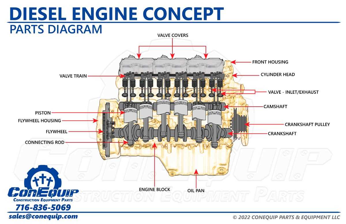
The exhaust framework plays a crucial role in directing and managing gases produced during combustion, ensuring both efficiency and environmental compliance. Understanding its components helps in grasping how this system enhances performance and reduces harmful emissions.
| Component | Description |
|---|---|
| Manifold | Collects gases from multiple cylinders and directs them into the exhaust pipe. |
| Catalytic Converter | Transforms harmful pollutants into less harmful emissions through chemical reactions. |
| Muffler | Reduces noise produced by the escaping gases, ensuring a quieter operation. |
| Exhaust Pipe | Channels exhaust gases away from the vehicle, preventing back pressure. |
Common Engine Diagram Symbols
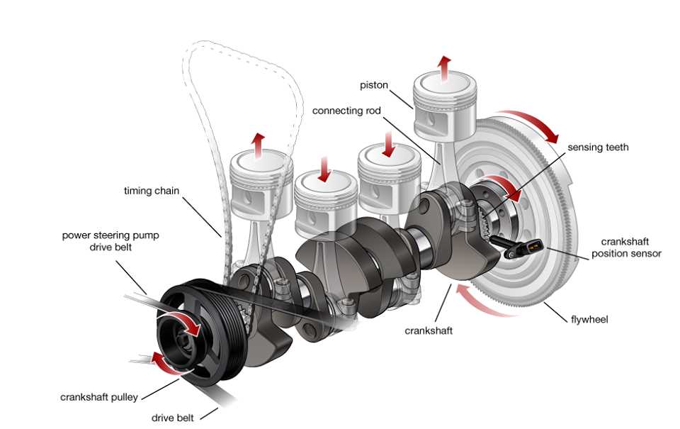
Understanding the visual language used in mechanical representations is essential for anyone engaged in automotive design or repair. These illustrations utilize specific symbols to convey complex information succinctly, allowing for easier interpretation of various components and their functions.
Basic Symbols
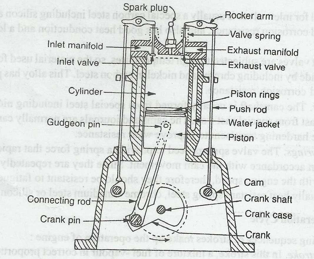
- Circle: Represents a basic unit or section.
- Arrow: Indicates direction of movement or flow.
- Square: Often used for junctions or connections.
Specialized Symbols
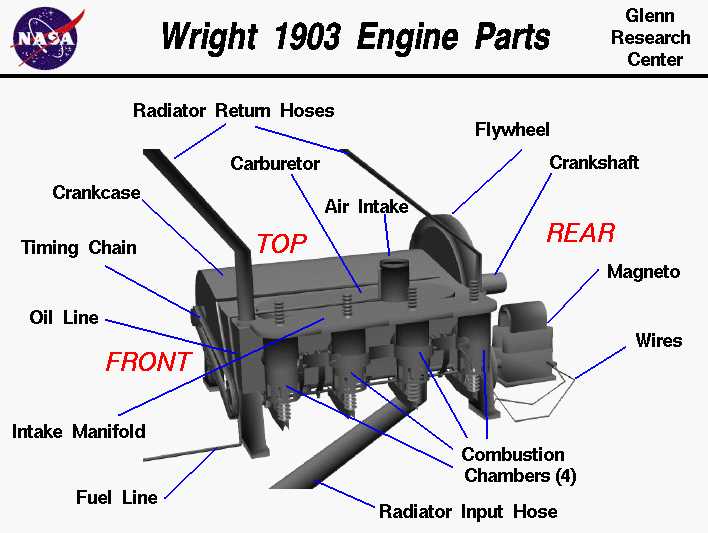
- Diamond: Signifies decision points or conditional operations.
- Triangle: Indicates warnings or important notes.
- Line: Represents pipes or connections between components.