Efficient operation of farming equipment depends on the smooth coordination of various elements that ensure optimal performance in different tasks. Understanding how each element functions together is essential for both maintenance and repair, especially in complex machinery used in agricultural processes.
In this guide, we will explore the intricate network of essential elements that contribute to the smooth functioning of your farming tools. Whether you’re dealing with issues related to mechanical efficiency or looking for a better understanding of how different components are structured, this resource will provide valuable insights.
Focusing on the detailed ar
Overview of Workmaster 75 Components
The essential structure of the machine is composed of various key elements that ensure its smooth and efficient operation. Each of these elements plays a critical role in delivering reliable performance and durability, making the equipment suitable for a wide range of tasks.
Key Mechanical Elements
- Engine assembly for powering the entire system
- Transmission unit providing smooth gear shifting
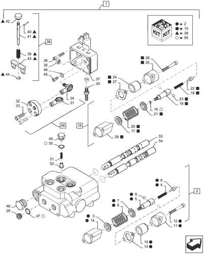
- Hydraulic system supporting essential lifting and movement functions
- Cooling components to regulate the system’s temperature
Additional Functional Units
- Steering and
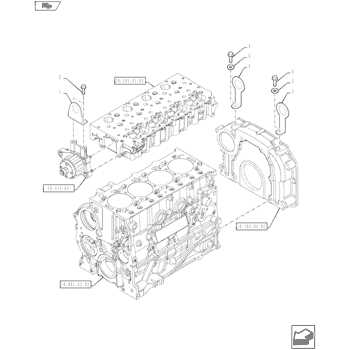
Engine Parts Layout
The structure of the motor is composed of several essential elements that ensure its smooth operation and efficiency. Each component plays a crucial role in maintaining performance, longevity, and proper functioning of the overall system. Understanding how these pieces fit together helps in the maintenance and troubleshooting of the unit.
- Cylinder Block – The core part that houses several key elements like pistons and cooling channels.
- Cylinder Head – A critical section that covers the top of the cylinders and manages air and fuel flow.
- Pistons – These convert fuel energy into mechanical power by moving up and down within the cylinders.
- Crankshaft – This element transforms the linear motion of the pistons into rotational movement.
- Steering Knuckles
- Spindle Assembly
- Wheel Hubs
- Axle Shaft
- Suspension Arms
- Refer to the service manual for specifications and visual guides.
- Inspect each component for any signs of wear or damage.
- Use online resources or forums for additional support and diagrams.
- Climate Control
- Instrumentation Panel
- Seating Arrangements
- Storage Solutions
- Climate Control: Maintains an optimal temperature for comfort during extended use.
- Instrumentation Panel: Provides essential information at a glance, including speed, fuel level, and other critical metrics.
- Seating Arrangements: Designed to support ergonomic posture, reducing fatigue during long working hours.
- Storage Solutions: Offers convenient spaces for tools and personal items, keeping the cabin organized.
Transmission System Diagram
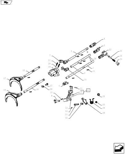
The transmission mechanism plays a crucial role in transferring power from the engine to the wheels, ensuring smooth and efficient movement. Understanding how the various components work together allows for better maintenance and troubleshooting of the system. This section provides an overview of the key elements involved in this essential system, focusing on the arrangement and interaction of gears, shafts, and other crucial parts.
Key components in the transmission system include the main drive mechanism, gear sets, and connecting shafts. These elements are responsible for regulating speed and torque, adapting to different operational needs. Additionally, certain auxiliary parts ensure the smooth transition between gears, enhancing overall efficiency.
By studying the arrangement of these components, one can gain insights into the system’s functionality, allowing for timely adjustments and repairs when necessary.
Hydraulic System Configuration
The hydraulic system is designed to deliver optimal power for various operations, ensuring smooth performance across multiple tasks. The arrangement of its components allows fluid control, maintaining efficiency and reliability throughout its usage. Proper understanding of this setup is crucial for maintaining performance under different working conditions.
Pumps are essential in the process, pushing fluid through the system to create the necessary force. Depending on the design, a single or dual-pump configuration may be utilized, each providing distinct advantages in terms of pressure and flow.
Another key component is the valve, which directs the hydraulic fluid to the appropriate areas, allowing precise control over the system. The efficiency of these valves impacts overall performance and response times during operation.
Additionally, cylinders
Steering Mechanism Breakdown
The steering system is a crucial component that ensures the proper control and maneuverability of any vehicle. Understanding the arrangement and functionality of its elements is essential for maintaining effective operation. This section provides a clear view of how various elements within the steering setup work together to deliver precise control.
Component Description Steering Wheel The main interface used by the operator to control direction. Electrical Wiring Overview
This section provides a comprehensive understanding of the electrical connections and components essential for optimal operation. It emphasizes the significance of a well-organized wiring system in ensuring reliability and efficiency in machinery performance.
Key Components of Electrical Systems
At the heart of any electrical setup are several vital elements. These include cables, connectors, and switches. Each component plays a crucial role in maintaining proper electrical flow, enabling devices to function seamlessly. Understanding these parts can aid in troubleshooting and maintenance.
Importance of Wiring Schematics
Wiring schematics are invaluable for diagnosing issues and ensuring proper installations. They provide a visual representation of connections, facilitating easier identification of potential problems. Familiarity with these diagrams can enhance the efficiency of repair processes and prevent future complications.
Fuel System Components
The fuel system is essential for the efficient operation of an engine, ensuring that the right amount of fuel is delivered for combustion. Understanding the various elements involved in this system can help maintain performance and longevity.
Key Elements
This system comprises several vital components, each playing a crucial role in fuel delivery and management. These parts work together to provide the necessary fuel for optimal engine function.
Component Overview
Component Description Fuel Tank Stores the fuel before it is sent to the engine. Fuel Pump Moves fuel from the tank to the engine at the required pressure. Fuel Filter Cleans the fuel before it enters the engine to prevent clogging. Injector Atomizes the fuel for optimal combustion within the engine cylinders. Cooling System Design
The cooling system is a crucial component in maintaining optimal performance and longevity of any machinery. Its primary function is to regulate temperature, preventing overheating while ensuring efficient operation. An effectively designed cooling mechanism not only enhances reliability but also contributes to overall fuel efficiency.
Typically, this system comprises several key elements, including radiators, coolant pathways, and fans. The radiator serves as the core unit, dissipating heat absorbed from the engine through a liquid coolant. This fluid circulates through the engine, absorbing excess heat before returning to the radiator for cooling. Proper flow rates and temperature regulation are essential to ensure the system operates effectively under varying loads and environmental conditions.
Incorporating advanced materials and design techniques can significantly improve the thermal management of the system. For example, using lightweight, corrosion-resistant materials enhances durability and efficiency. Additionally, integrating sensors for real-time temperature monitoring allows for adjustments to maintain optimal operating conditions, further ensuring the longevity and effectiveness of the cooling system.
Brake Assembly Diagram
This section provides an overview of the braking system components, illustrating their arrangement and interaction within the machinery. Understanding these elements is crucial for effective maintenance and troubleshooting.
Component Description Brake Pedal Initiates the braking process by applying pressure to the hydraulic system. Brake Master Cylinder Converts pedal force into hydraulic pressure, sending fluid to the brake assemblies. Brake Lines Transport hydraulic fluid from the master cylinder to the brake components. Brake Calipers Clamp onto the brake pads to create friction against the brake disc, slowing the vehicle. Brake Pads Friction materials that press against the brake disc, generating the necessary stopping power. Brake Disc A rotating component that the pads clamp onto, converting kinetic energy into heat. Front Axle Parts Identification
Understanding the components of the front axle assembly is crucial for effective maintenance and troubleshooting. Each element plays a significant role in ensuring the smooth operation of the vehicle, and proper identification can aid in repairs and replacements.
Main Components
Identification Tips
Rear Hitch Mechanism Layout
The rear coupling system is a crucial component that facilitates the attachment of various implements to agricultural machinery. This mechanism ensures that the equipment can be securely connected while allowing for ease of operation and maneuverability in different agricultural tasks.
Components of the Rear Hitch
The primary elements of the rear coupling system include the drawbar, link arms, and mounting brackets. These components work together to provide stability and support during operation. The drawbar connects the implement to the vehicle, while the link arms adjust the height and angle for optimal performance.
Functionality and Adjustment
This system allows for various adjustments to accommodate different types of implements. By modifying the height and angle, operators can ensure that the connected equipment functions effectively across various terrains and tasks. Proper calibration of these components is essential for achieving the best results.
Cabin Interior Systems
The interior environment of a vehicle plays a crucial role in ensuring operator comfort and efficiency. Various systems are integrated within the cabin to enhance the overall user experience, providing essential functionalities that facilitate effective operation.
Key Components
Functional Features
Maintenance Points on Workmaster 75
Regular upkeep of agricultural machinery is essential to ensure optimal performance and longevity. Proper attention to various components can significantly enhance efficiency and reduce the risk of breakdowns. This section outlines key areas to focus on for effective maintenance.
One crucial aspect is the inspection of fluid levels, including engine oil, hydraulic fluid, and coolant. Maintaining appropriate levels helps prevent overheating and ensures smooth operation of moving parts. Additionally, checking for leaks and addressing them promptly can avoid costly repairs.
Another important area is the examination of filters. Air, fuel, and hydraulic filters should be cleaned or replaced as needed to ensure that the engine operates efficiently and to prevent contaminants from causing damage. Regular filter maintenance contributes to better fuel economy and overall performance.
Furthermore, routine checks of belts and hoses are vital. Inspecting these components for wear and tear can help prevent unexpected failures during operation. Replacing worn-out belts and hoses before they break can save time and money in the long run.
Lastly, it is essential to maintain the cleanliness of the machine. Regular washing and removal of debris not only enhance the appearance but also prevent corrosion and promote proper cooling. A clean machine is more reliable and can operate more efficiently in various conditions.