
Propulsion technology is a marvel of engineering that powers the rapid transportation of people and cargo across vast distances. The components within these systems work in harmony to achieve incredible speeds and high efficiency, allowing both commercial and military applications to push the limits of what is possible. This section explores the intricate design and functionality of various elements that contribute to the overall performance of these advanced machines.
The internal structure includes several interconnected elements, each with a critical role in converting energy into forward motion. Some modules focus on drawing in and compressing air, while others ignite fuel mixtures to create high-pressure flows. A careful balance between power output and fuel efficiency is maintained to ensure smooth and safe operation under various conditions.
From intake mechanisms to exhaust sections, each part serves a unique purpose in the propulsion process. These components must withstand extreme temperatures and pressures, demanding robust materials and precise engineering. The following sections delve into each element’s role, highlighting their importance and how they contribute to the overall system’s performance and reliability.
Jet Engine Components Overview

This section provides an understanding of the essential mechanisms and systems working together to deliver propulsion. Each component plays a distinct role, ensuring efficient operation by converting energy into thrust while maintaining stability and performance.
Primary Sections and Their Functions
- Intake System: Facilitates smooth air entry and prepares it for further stages.
- Compression Unit: Increases air density, making the process more efficient for energy production.
- Combustion Chamber: Introduces fuel and ignites it, releasing high-pressure gases.
- Turbine Assembly: Extracts energy from gases to power other systems.
- Exhaust Mechanism: Directs gases outward, producing the force needed for propulsion.
Support Systems and Safety Components
- Cooling Networks: Regulate temperatures to prevent overheating during operation.
- Control Units: Monitor and adjust performance to match desired conditions.
- Lubrication System: Ensures smooth movement of internal parts, minimizing friction.
- Noise Reduction Modules: Lower sound levels, improving environmental impact.
The combination of these systems ensures optimal performance, balancing power, efficiency, and safety throughout operation.
Core Structure and Functionality
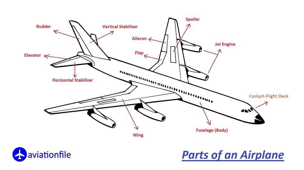
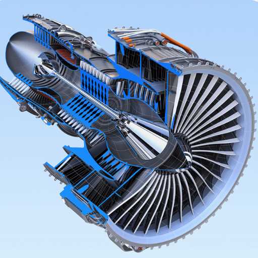
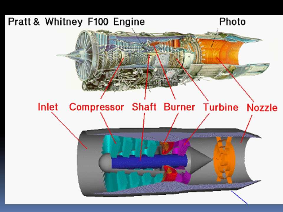
The heart of the propulsion system is designed to efficiently channel energy through multiple interconnected components. Its layout prioritizes optimal performance by managing air compression, energy transfer, and propulsion generation. Every element plays a role in maintaining stability, enhancing thrust, and ensuring smooth operation under various conditions.
| Component | Purpose |
|---|---|
| Compressor | Increases air pressure for improved energy conversion. |
| Combustion Chamber | Mixes fuel and air to produce controlled bursts of energy. |
| Turbine | Extracts energy from heated gases to drive the compressor. |
| Nozzle | Directs the flow to generate forward momentum. |
This intricate design ensures that the propulsion system achieves both power and efficiency, balancing force output and fuel consumption across all phases of operation.
Air Intake Mechanism Design
The design of the air intake mechanism focuses on ensuring smooth and efficient airflow into the system. It aims to reduce turbulence, regulate pressure levels, and enhance overall performance. Proper alignment and structure are critical to maintaining a stable flow, minimizing drag, and optimizing energy conversion.
Flow Optimization and Stability
To achieve optimal results, the mechanism is shaped to guide air steadily through various sections without disruptions. Curved surfaces, inlets, and channels are often employed to balance the incoming stream, ensuring consistent pressure across the entire pathway. Any imbalance in this process can impact functionality and reduce efficiency.
Temperature and Pressure Regulation
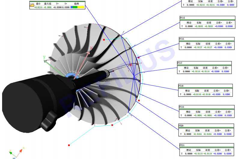
Maintaining suitable temperature and pressure conditions is essential. The air intake mechanism may incorporate elements that regulate these parameters before the air reaches other components. This process not only ensures better performance but also prevents thermal stress and pressure fluctuations, which could negatively affect the system’s stability.
Compressor Blade Arrangement
The configuration of rotating and stationary elements plays a key role in ensuring smooth airflow and efficient compression. These components are meticulously organized to achieve optimal performance by guiding the incoming air through multiple stages, gradually increasing pressure.
- Rotating Blades: Mounted on a shaft, these elements accelerate the air as it flows through the system, enhancing momentum with each rotation.
- Stator Vanes: Positioned between rotating sections, these guide the airflow, reducing turbulence and aligning it for the next compression phase.
- Multi-Stage Arrangement: Systems often consist of several compression stages, with each step contributing incrementally to the total pressure increase.
- Aerodynamic Design: Blades are engineered with precise curvature and angle to minimize energy loss and maximize efficiency.
Maintaining the balance between rotational speed and airflow is essential for reliable operation. Each component in the arrangement must function seamlessly to prevent energy dissipation, ensuring consistent pressure build-up and avoiding potential flow disruptions.
Combustion Chamber Elements
The section explores the essential components involved in the internal combustion process, focusing on how each element contributes to efficient energy conversion. The design of these components plays a crucial role in sustaining controlled ignition and maintaining performance under high temperatures and pressures.
Main Structural Components

Several key elements form the core of the combustion process. The casing provides the necessary housing to contain the heat and pressure. Airflow channels ensure a steady intake and circulation of air for optimal combustion. Additionally, seals and linings protect the structure from thermal stress, extending the lifespan of the system.
Ignition and Flow Regulation
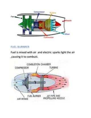
Reliable ignition sources and fuel injectors are indispensable for proper operation. The injectors precisely control the mixture ratio, while flame holders stabilize the burning process. Efficient airflow management ensures the necessary oxygen supply, supporting complete fuel combustion.
| Component | Function |
|---|---|
| Fuel Injector | Controls the delivery and distribution of fuel into the chamber. |
| Ignition Source | Initiates the combustion process at startup. |
| Flame Holder | Stabilizes the flame, ensuring steady burning under various conditions. |
| Casing | Contains the heat and pressure, providing structural support. |
| Seals and Linings | Protect internal parts from thermal damage and wear. |
Exhaust Nozzle Configuration
The design of the exhaust outlet plays a crucial role in optimizing performance and efficiency. By controlling the flow of gases, it contributes significantly to thrust generation and overall propulsion effectiveness. Various configurations exist, each tailored to specific operational needs and environmental considerations.
| Configuration Type | Description |
|---|---|
| Convergent | This type narrows the passageway, increasing gas velocity and providing a higher thrust output at subsonic speeds. |
| Divergent | Expanding the flow path allows for pressure recovery and increased efficiency, particularly at supersonic speeds. |
| Variable Geometry | Adjustable designs enable optimal performance across a range of speeds by altering the nozzle shape as needed. |
| Dual-Mode | This configuration can switch between different modes, allowing for flexibility in varying operational conditions. |
Understanding these configurations is essential for engineers and designers seeking to enhance performance and meet specific operational demands.
Turbine Blade Materials
The choice of materials for turbine blades plays a critical role in their performance and durability. These components must withstand extreme conditions, including high temperatures, pressure, and corrosion, while maintaining structural integrity. Selecting the appropriate substances is essential to ensure efficiency and longevity in high-performance applications.
Key Material Types

- Superalloys: Typically composed of nickel or cobalt, these alloys provide excellent strength and resistance to deformation at elevated temperatures.
- Ceramics: Advanced ceramic materials offer high thermal resistance and can be utilized in various applications to enhance performance.
- Composites: Combining different materials can yield components that are both lightweight and strong, improving overall efficiency.
Factors Influencing Material Selection
- Temperature Resistance: Materials must endure high thermal loads without compromising strength.
- Corrosion Resistance: The ability to resist oxidation and environmental degradation is crucial for longevity.
- Manufacturability: Ease of fabrication and adaptability in production processes affect material choice.
In conclusion, the selection of appropriate materials for turbine blades is vital to achieving optimal performance and reliability in challenging operational conditions. Each material offers unique properties that contribute to the overall effectiveness of the blade design.
Fuel Delivery System Layout
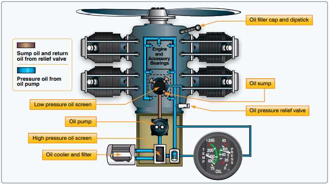
The fuel delivery framework is a critical aspect of any high-performance propulsion system. It ensures that the proper amount of fuel is supplied to the combustion chamber at the right pressure and temperature. This system is designed to maximize efficiency and reliability while minimizing the risk of failure during operation.
The layout typically includes several key components, such as pumps, filters, and control valves. These elements work together to transport fuel from storage tanks to the combustion area. Pumps are essential for moving the fuel, while filters remove any contaminants that could disrupt the combustion process. Control valves play a vital role in regulating fuel flow, ensuring optimal performance under various operating conditions.
Additionally, the arrangement of these components is carefully engineered to facilitate ease of maintenance and inspection. Proper positioning allows for quick access to critical elements, thereby reducing downtime during servicing. A well-designed fuel delivery system is fundamental for achieving the desired performance and safety standards in any advanced propulsion application.
Lubrication and Cooling Systems
The performance and longevity of high-speed propulsion systems rely heavily on efficient lubrication and cooling mechanisms. These systems are designed to minimize friction and heat buildup, ensuring optimal functionality under extreme conditions. Proper maintenance of these systems is crucial for reliability and efficiency.
Lubrication plays a vital role in reducing wear and tear on moving components. By creating a protective film, it allows parts to glide smoothly against each other, preventing direct contact that could lead to damage. Additionally, effective lubrication helps dissipate heat generated during operation, contributing to overall thermal management.
Cooling systems are equally important, as they regulate temperatures to prevent overheating. These mechanisms often utilize a combination of air and liquid cooling methods to maintain ideal operating conditions. Heat exchangers, for instance, transfer excess heat away from critical components, while fans or pumps circulate coolant to ensure even temperature distribution.
In summary, the integration of advanced lubrication and cooling systems is essential for maintaining the efficiency and reliability of high-speed propulsion technologies. Properly functioning systems not only enhance performance but also extend the lifespan of vital components.
Noise Reduction Strategies
In various mechanical systems, minimizing sound output has become a crucial aspect of design and operation. Effective approaches aim to reduce unwanted auditory emissions while maintaining performance and efficiency. This section explores several methodologies to achieve significant attenuation of noise in these complex assemblies.
Design Modifications
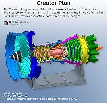
Implementing innovative design changes can greatly influence sound levels. For instance, incorporating sound-absorbing materials within the structure can dampen vibrations and reduce resonance. Additionally, optimizing shapes and configurations can minimize turbulence, which is often a source of excess noise. These alterations contribute not only to quieter operation but also enhance overall system durability.
Active Noise Control
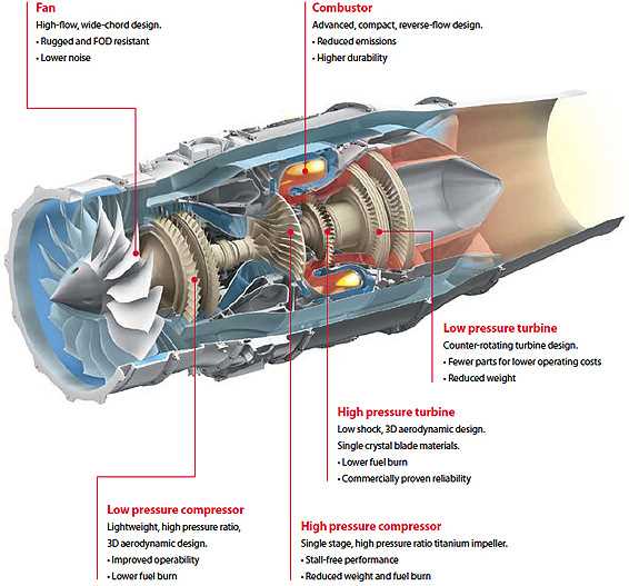
Another promising technique involves the use of active noise cancellation technologies. By deploying microphones and speakers strategically, systems can detect and counteract undesirable sound waves in real-time. This proactive method effectively neutralizes specific frequencies, leading to a more serene operational environment. Such advancements represent a significant leap forward in the quest for quieter machinery.
Control Systems and Sensors
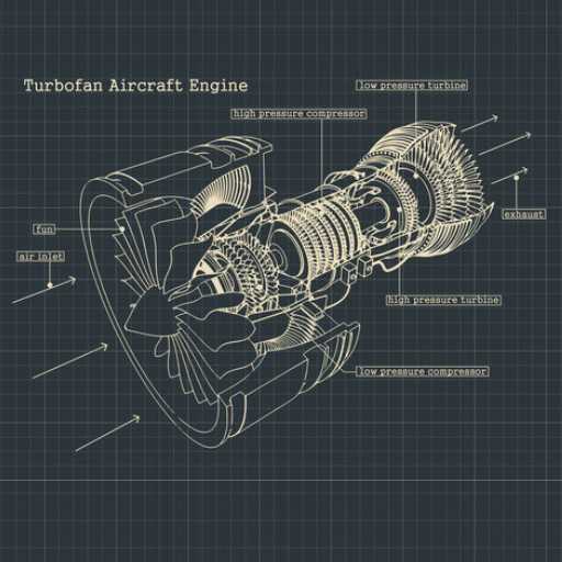
The effectiveness of modern propulsion systems relies heavily on sophisticated control mechanisms and advanced detection devices. These components work in harmony to ensure optimal performance, safety, and efficiency. Through precise monitoring and management, they contribute to the overall functionality of the system, allowing for adjustments in real-time based on various operating conditions.
Control systems integrate algorithms and logic to oversee the operation of the propulsion unit. They manage variables such as thrust levels, temperature, and pressure, ensuring that the system operates within designated parameters. Feedback loops enable continuous assessment, allowing the system to respond dynamically to any deviations from normal functioning.
Sensors play a crucial role by gathering essential data about the operating environment and system performance. These devices detect changes in temperature, pressure, vibration, and other critical factors, providing valuable information for the control systems. The accuracy and reliability of these sensors are paramount, as they directly influence decision-making processes and system responses.
In summary, the interplay between control systems and sensors is vital for the optimal operation of propulsion mechanisms. Together, they enhance safety, improve performance, and facilitate advancements in technology, enabling the development of more efficient and reliable systems.
Maintenance Requirements and Challenges
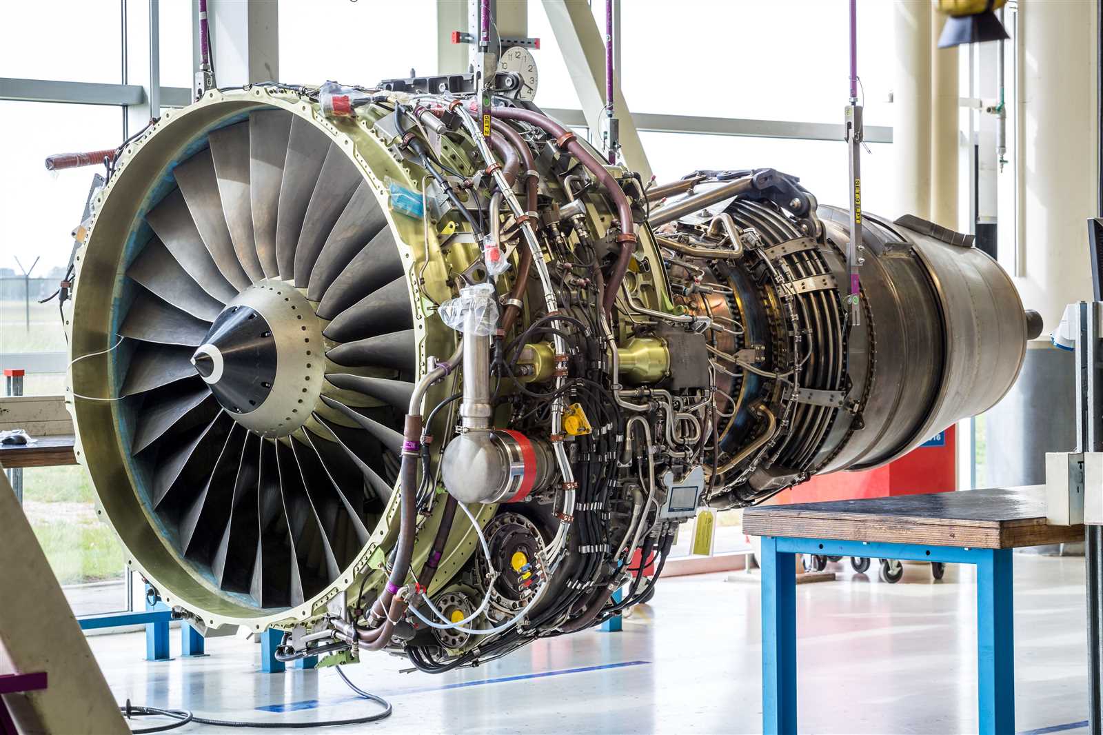
Ensuring optimal performance and longevity of complex mechanical systems necessitates a thorough understanding of their upkeep necessities and potential obstacles. Regular inspections, timely repairs, and preventive measures are essential to maintaining functionality and safety.
Key requirements for effective maintenance include:
- Routine inspections to identify wear and tear.
- Calibration of components to ensure precise operation.
- Regular cleaning to prevent contaminants from causing damage.
- Timely replacement of worn-out components to avoid failures.
However, several challenges complicate these maintenance tasks:
- Accessibility: Many components are located in hard-to-reach areas, making inspections and repairs difficult.
- Technical Expertise: Specialized knowledge is required for proper assessment and repair, necessitating trained personnel.
- Cost Considerations: Maintenance can be costly, with high expenses associated with labor and replacement parts.
- Compliance: Adhering to stringent regulations and standards can be time-consuming and demanding.
Addressing these maintenance requirements and challenges is vital for ensuring the reliable operation of mechanical systems, ultimately contributing to enhanced performance and safety.