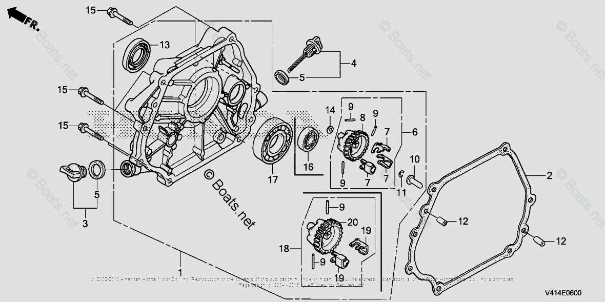
Maintaining complex outdoor equipment requires a clear understanding of how various mechanisms work together to ensure optimal performance. Each element plays a crucial role in the overall functionality, making it essential to be familiar with their placement and purpose. Knowing the specifics of each component aids in the timely replacement and repair of any malfunctioning elements, ensuring reliable operation over time.
In this guide, we will take a closer look at the internal structure of a robust snow-clearing machine. From the intricate moving mechanisms to the more subtle mechanical parts, this exploration will help shed light on the importance of routine maintenance. It is important to familiarize yourself with the placement and connectivity of these elements to prolong the machine’s operational lifespan and ensure safety during use.
Whether you are performing routine maintenance or troubleshooting specific issues, understanding the relationship between various mechanical elements is vital. This insight not only helps with repairs but also provides a deeper knowledge of how these devices
Overview of Honda HSS928A Components
The system is built around several key elements, each designed to perform specific tasks. These interconnected components ensure reliable operation, working in harmony to provide optimal performance. Below is a closer look at the primary elements, their roles, and how they contribute to the overall functionality.
Key Mechanical Elements
- Engine Unit – The central powerhouse that drives the entire system, designed for durability and efficiency in various conditions.
- Auger Mechanism – A critical part responsible for handling material, designed to withstand heavy use and efficiently transfer the load.
- Transmission – Facilitates smooth power distribution, ensuring the right balance between speed and force for efficient operation.
Control and Adjustment Features
- Steering System – Allows for precise control, enabling smooth maneuverability and
Key Elements of Snowblower Construction
Understanding the fundamental components of a snow removal machine is crucial for efficient operation and maintenance. Various elements work in harmony to ensure optimal performance, from the engine to the auger and the chute. Each part plays a significant role in the overall functionality, allowing for effective snow clearing even in challenging conditions.
Core Components
The primary assembly of any snow-clearing apparatus includes the engine, which provides the necessary power to operate all functions. The auger serves as the first point of contact with the snow, designed to chop and lift the material for efficient transport. Following this, the impeller propels the snow through the discharge chute, ensuring that it is expelled far from the cleared area.
Additional Features
In addition to these core elements, various accessories and adjustments enhance usability. For instance, adjustable chutes allow the operator to control the direction of the expelled snow, while user-friendly controls improve the overall handling of the machine. Regular maintenance of these components is essential to prolong the life of the equipment and maintain high performance during winter months.
Understanding the Engine and Power System
The engine and power system form the heart of any outdoor machinery, serving as the primary source of energy that drives performance. A thorough comprehension of these components is crucial for effective operation and maintenance. This section delves into the fundamental aspects that influence efficiency, durability, and overall functionality.
The engine comprises various essential parts that work in harmony to generate power. Understanding the interactions between these components is vital for troubleshooting and ensuring optimal performance. Key elements include the fuel delivery system, ignition components, and cooling mechanisms.
Component Description Fuel System Responsible for delivering the appropriate amount of fuel to the engine for combustion. Ignition System Initiates the combustion process, ensuring that the fuel-air mixture ignites at the right moment. Cooling System Regulates engine temperature to prevent overheating during operation. Exhaust System Facilitates the safe expulsion of combustion gases from the engine. Regular inspection and maintenance of these components enhance reliability and extend the lifespan of the equipment. Being attentive to any signs of wear or malfunction can prevent costly repairs and ensure smooth operation in various conditions.
Detailed Look at the Auger Assembly
The auger assembly is a crucial component in snow removal equipment, designed to efficiently collect and transport snow away from the operating area. Understanding its structure and functionality can enhance maintenance practices and ensure optimal performance during use.
Key Components of the Auger Assembly
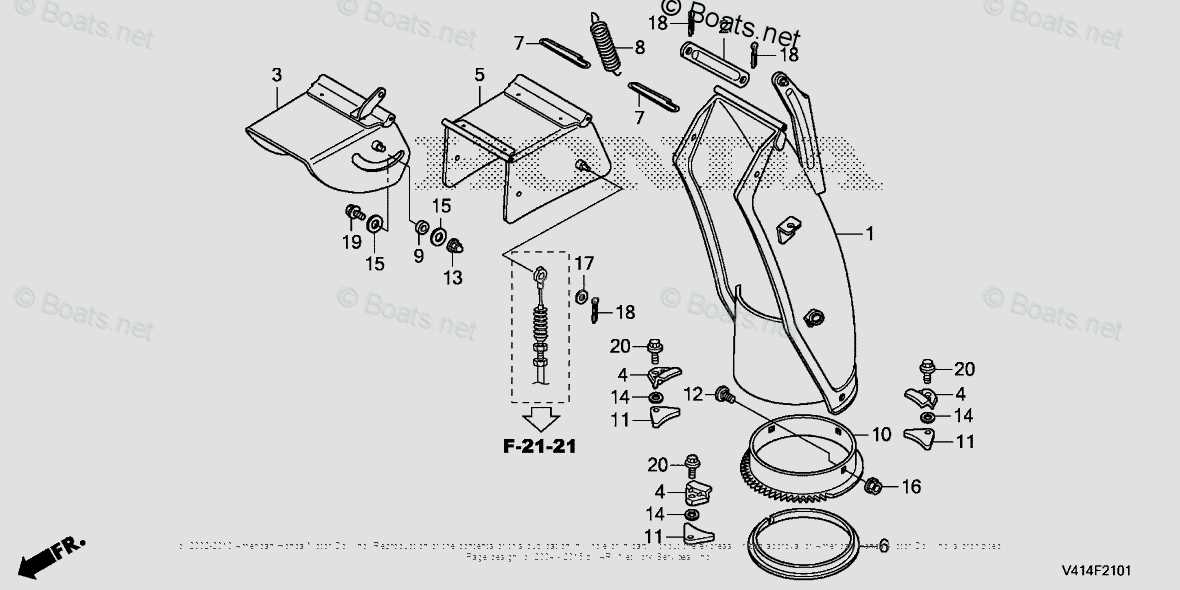
This assembly typically consists of several essential elements, including the auger blades, housing, and drive system. The auger blades are responsible for breaking up and lifting the snow, while the housing protects the internal mechanisms and directs the flow of snow. The drive system powers the auger rotation, facilitating smooth operation.
Maintenance Tips for Optimal Performance
Regular inspection and maintenance of the auger assembly are vital to prolong its lifespan. Ensuring that the blades are sharp and free from damage can significantly improve efficiency. Additionally, lubricating the moving parts and checking for any signs of wear can help prevent mechanical failures and enhance overall functionality.
Transmission Mechanism and Its Role
The transmission system is a crucial component that facilitates the transfer of power from the engine to the wheels. Its primary function is to ensure that the machine operates efficiently under varying conditions by adjusting the output speed and torque. This intricate assembly enables smooth operation and enhances the overall performance of the equipment.
Functionality and Importance
At its core, the transmission mechanism serves as a mediator between the engine’s power and the operational demands of the device. It allows for optimal performance by modifying the gear ratios, which can significantly impact acceleration and speed. By efficiently managing these elements, the mechanism contributes to fuel efficiency and reduces wear on the engine.
Components and Their Interactions
The system comprises several integral parts, including gears, shafts, and clutches, all of which work in harmony to deliver power effectively. Each component plays a distinct role, with gears providing different torque levels, while clutches facilitate smooth engagement and disengagement. Understanding these interactions is essential for maintenance and troubleshooting, ensuring the longevity and reliability of the machine.
Exploring the Control Panel Layout
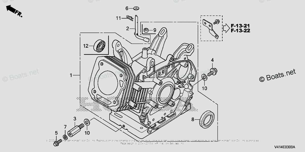
The control interface of this equipment plays a crucial role in ensuring efficient operation and user convenience. Understanding the arrangement of buttons, switches, and indicators is essential for optimal performance. This section delves into the various components of the control panel, highlighting their functions and significance.
Key Components of the Control Interface
- Power Switch: The primary element for turning the machine on and off.
- Throttle Control: Adjusts the engine speed for varying operational needs.
- Choke Lever: Assists in starting the engine under different conditions.
- Safety Features: Includes emergency stop buttons and indicators for safe operation.
- Operation Mode Selector: Allows users to switch between different operational settings.
Understanding the Functionality
Each component within the control panel is designed to enhance usability. For instance, the throttle control allows for precise speed adjustments, ensuring the user can adapt to various tasks effectively. The safety features are paramount, providing peace of mind by ensuring the equipment can be halted immediately if necessary. Overall, familiarizing oneself with these controls is vital for maximizing the efficiency and safety of the machine.
Fuel System Parts and Maintenance
The efficiency of a machine’s fuel delivery mechanism is crucial for optimal performance and longevity. Regular inspection and upkeep of these components ensure smooth operation and can prevent costly repairs down the line. Understanding the various elements involved and their roles is essential for effective maintenance.
Key Components of the Fuel Delivery Mechanism
The fuel system consists of several critical components that work together to supply energy to the engine. Each part plays a specific role in the overall function of the system.
Component Description Fuel Tank Stores fuel and provides a reservoir for the system. Fuel Pump Transfers fuel from the tank to the engine, maintaining the necessary pressure. Fuel Filter Removes impurities and debris from the fuel before it reaches the engine. Carburetor/Fuel Injector Mixes fuel with air for combustion, optimizing the engine’s performance. Fuel Lines Transport fuel between components, ensuring a continuous flow. Maintenance Practices
Regular maintenance of the fuel system is essential for preventing issues and ensuring efficient operation. Key practices include routine inspections, timely replacements of filters, and monitoring fuel quality. Keeping fuel lines clear and checking for leaks can further enhance the system’s reliability.
Chute Rotation and Directional Parts
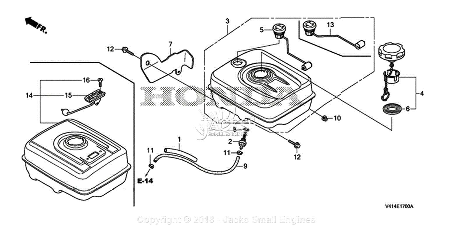
The mechanisms responsible for the rotation and direction of the discharge chute are essential for effective snow management. These components enable users to control where the cleared snow is directed, enhancing both efficiency and convenience during operation.
Rotation Mechanism: This system typically includes a pivot point that allows the chute to turn horizontally. The rotational capabilities are crucial for adjusting the angle of discharge, providing flexibility based on the specific requirements of the task.
Directional Controls: The controls for the chute’s direction are often located within easy reach of the operator. These may consist of levers or buttons that facilitate quick adjustments, ensuring that the snow can be thrown precisely where needed.
Maintenance of these components is vital to ensure smooth operation. Regular checks can prevent issues that might hinder functionality, allowing for consistent performance during winter months.
Track System and Movement Components
The functionality of a snow-clearing machine relies heavily on its track assembly and motion elements. These components work cohesively to ensure efficient mobility across various terrains, facilitating optimal performance even in challenging conditions. Understanding the key parts involved in this system is essential for maintenance and troubleshooting.
Key Elements of the Track System
- Tracks: The continuous bands provide traction and stability, allowing the machine to navigate snow and ice effectively.
- Idler Wheels: These wheels support the weight of the tracks and help in guiding their movement.
- Drive Wheels: Connected to the engine, these wheels propel the tracks, enabling forward and backward motion.
- Sprockets: These toothed wheels engage with the track links, converting the engine’s power into movement.
Movement Mechanisms
- Transmission: This system transfers power from the engine to the drive wheels, allowing for controlled movement.
- Steering Controls: Operators can maneuver the machine using levers or pedals, which adjust the speed and direction of the tracks.
- Suspension System: It absorbs shocks and stabilizes the unit during operation, improving comfort and control.
Proper understanding and maintenance of these components are crucial for ensuring the longevity and effectiveness of the equipment. Regular inspections and timely replacements contribute to optimal operation and reliability during winter tasks.
Electrical System Diagram and Wiring
This section provides a comprehensive overview of the electrical configuration and circuitry involved in the machine’s operation. Understanding the layout of electrical components is essential for effective troubleshooting and maintenance. It encompasses various elements, including wiring connections, power distribution, and the integration of safety features.
Key Components and Connections
The electrical setup consists of several crucial components that work in harmony to ensure efficient functionality. These include the battery, ignition system, and various sensors. Each component must be connected correctly to maintain optimal performance.
Wiring Overview
Proper wiring is fundamental for the reliability of the system. This section outlines the various connections and their significance in the overall functionality of the equipment.
Component Description Connection Type Battery Stores electrical energy for starting and powering components Direct connection to ignition and electrical system Ignition Switch Controls the flow of electricity to the engine Momentary contact switch Alternator Generates electrical power while the engine is running Connected to battery and electrical load Sensors Monitor various parameters for optimal performance Wired connections to the control unit Frame and Structural Components Explained
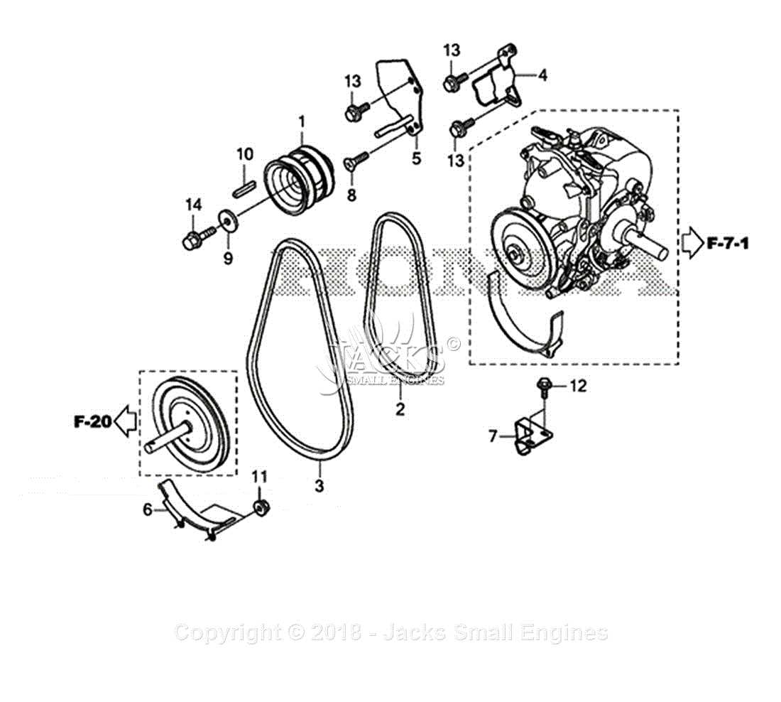
The framework and structural elements of any machinery play a vital role in ensuring stability, durability, and functionality. These components work together to create a robust foundation that supports the entire system, allowing for effective operation under various conditions. Understanding their layout and functions is essential for maintenance and repair, ensuring optimal performance and longevity.
Key Structural Elements
Structural components can vary in design and material, but their primary purposes remain consistent. They are engineered to withstand mechanical stresses while providing essential support. Some common elements include the chassis, supports, and reinforcements, which all contribute to the overall integrity of the system.
Understanding the Framework Layout
The arrangement of structural parts is crucial for achieving a balanced design. Proper alignment and connection among components enhance stability and facilitate smooth operation. Regular inspection of these elements is recommended to identify any signs of wear or damage, ensuring that the framework remains functional.
Component Function Material Chassis Provides the main structure and support Steel or aluminum Support Brackets Holds and stabilizes various components Steel Reinforcements Enhances strength and rigidity Composite or metal Troubleshooting Common Part Failures
Identifying and resolving issues with various components can significantly enhance the performance and longevity of your equipment. Understanding potential failures and their symptoms is essential for effective maintenance and timely repairs. This section aims to provide insights into frequent malfunctions and offer guidance on how to address them efficiently.
Identifying Symptoms
When components begin to malfunction, specific signs may become evident. Recognizing these early can prevent further damage and costly repairs. Common indicators of issues include unusual noises, difficulty in operation, or visible wear and tear. It is crucial to observe the equipment closely during operation to catch these signs promptly.
Common Failures and Solutions
Common Issue Possible Cause Recommended Action Unresponsive operation Faulty ignition system Check spark plug connections and replace if necessary. Excessive vibration Worn bearings or loose components Inspect and tighten all connections; replace damaged bearings. Poor performance Clogged filters or stale fuel Replace filters and use fresh fuel to ensure optimal function.