A well-structured schematic offers invaluable insight into the inner workings of a machine, providing clarity on how individual elements interconnect to form a cohesive system. Understanding these layouts enables users to identify key components, ensuring smooth operation and timely interventions when needed.
By referring to detailed illustrations, operators and technicians can streamline upkeep procedures, minimizing downtime and avoiding unnecessary repairs. Accurate schematics play a critical role in maintaining complex equipment, facilitating the process of diagnosing issues and finding appropriate replacements.
From mechanical assemblies to electrical systems, accessing the correct configurations helps improve workflow efficiency. With the right references at hand, routine inspections, adjustments, and part substitutions become far more manageable, empowering users to keep their machines running at peak performance.
Essential Components of Kubota B2301
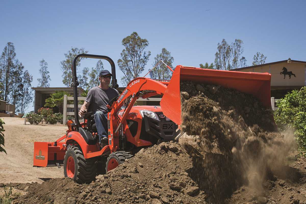
This section explores the primary elements crucial for the efficient operation of a compact utility vehicle. Each component plays a key role in ensuring smooth functionality, optimal performance, and durability in agricultural and landscaping tasks.
Core Mechanical Elements
The mechanical system includes a robust engine, transmission, and hydraulics. These parts work together to provide power and control, supporting heavy loads and maintaining reliable traction on various terrains. The cooling system ensures the engine operates within safe temperature limits during prolonged use.
Control and Operational Features
The steering mechanism, braking system, and driving controls allow precise maneuverability and safety. Instruments on the dashboard provide real-time feedback on performance metrics, ensuring the operator can make adjustments when necessary.
| Component | Function |
|---|---|
| Engine | Generates power for driving and hydraulic systems |
| Transmission | Transfers engine power to wheels |
| Hydraulics | Supports lifting and movement of attachments |
| Brakes | Ensures controlled stopping and safety |
| Steering | Allows precise navigation |
Overview of the Engine Assembly
The engine assembly serves as the core component of any machinery, ensuring the conversion of fuel into mechanical energy. This intricate system integrates multiple interconnected elements that work in harmony to achieve efficient performance. Understanding its structure helps in maintaining functionality and prolonging operational life.
Key Components within the Engine System
At the heart of the assembly lies the cylinder block, which houses essential mechanisms such as pistons and crankshafts. Precision-engineered valves control the intake of air and fuel, as well as the release of exhaust gases. Additionally, the cooling system and lubrication network play vital roles in preventing overheating and reducing wear.
Maintenance Insights and Troubleshooting
Regular inspection of belts, filters, and spark plugs ensures smooth operation. Paying attention to unusual sounds or changes in performance can help identify potential issues early. Routine upkeep not only enhances longevity but also minimizes the risk of unexpected downtime.
Transmission System Breakdown
The transmission system ensures smooth power delivery from the engine to the wheels, providing essential control over speed and torque. Understanding its components is crucial for maintenance and identifying potential issues before they escalate.
- Clutch Mechanism: Engages and disengages the engine from the drivetrain, allowing gear changes without damaging internal parts.
- Gearbox: Houses multiple gears that control speed and torque output based on the selected gear ratio.
- Driveshaft: Transmits rotational energy from the gearbox to the final drive system, ensuring consistent movement.
- Final Drive: Reduces the rotational speed further while increasing torque, optimizing power delivery to the wheels.
Maintaining proper lubrication, adjusting linkages, and timely inspection of seals help prolong the system’s lifespan. Regular checks ensure optimal performance and prevent costly repairs down the line.
Hydraulic Mechanism and Key Parts
The hydraulic system plays a crucial role in ensuring smooth operation and efficient power transfer in modern machinery. It utilizes fluid dynamics to convert mechanical energy into hydraulic pressure, enabling precise control of various functions. This section outlines the essential components involved in the hydraulic mechanism and their roles in maintaining seamless performance.
Main Components and Their Functions
- Pump: The pump generates the hydraulic pressure necessary to drive different actuators and motors.
- Control Valve: This component regulates the flow of hydraulic fluid, directing it to the appropriate sections of the system.
- Cylinders: Hydraulic cylinders convert fluid pressure into linear motion, often used for lifting or extending parts.
- Hoses and Pipes: These channels ensure smooth transmission of fluid throughout the system with minimal resistance.
- Reservoir: The reservoir stores the hydraulic fluid and helps maintain optimal pressure within the system.
Maintenance Tips for Optimal Performance
- Regularly inspect hoses and seals for signs of leaks or wear.
- Keep the fluid levels within recommended ranges to avoid pressure drops.
- Replace filters periodically to ensure clean fluid circ
Electrical System Overview and Wiring
The electrical system in agricultural equipment is designed to ensure reliable power distribution to essential components. A well-organized network of connections supports efficient operation by managing energy flow between the engine, control panels, lights, and sensors. Understanding the system layout helps diagnose issues and maintain peak performance.
Key Components of the Electrical Setup
- Battery: Stores electrical energy and supplies power to the starter and other systems.
- Alternator: Converts mechanical energy into electrical energy to recharge the battery during operation.
- Fuse Box: Protects electrical circuits by interrupting power in case of overloads.
- Control Switches: Manage the flow of electricity to lights, ignition, and other equipment.
Wiring and Connection Guidelines
- Ensure all wires are securely connected to avoid power loss or short circuits.
- Use color-coded wires to simplify troubleshooting and maintenance.
- Regularly inspect connectors for corrosion or loose fittings.
- Follow safety standards when installing additional components to prevent overloading.
By following these practices, the electrical system can remain operational and efficient, ensuring that machinery performs reliably under various conditions.
Cooling Unit and Radiator Structure
The cooling unit and radiator play a crucial role in maintaining optimal operating temperatures for machinery. Their design ensures efficient heat dissipation, preventing overheating and enhancing performance. Understanding the components and layout of these systems is essential for effective maintenance and troubleshooting.
Components of the Cooling System
The cooling system comprises several key elements, including the radiator, cooling fans, hoses, and water pump. Each component works in harmony to circulate coolant and dissipate heat. The radiator, typically constructed from aluminum or copper, features a network of tubes and fins that maximize surface area for heat exchange.
Functionality and Maintenance
Proper functionality of the cooling unit is vital for the longevity of the equipment. Regular inspection of hoses for wear and tear, ensuring that the coolant level is adequate, and cleaning the radiator from debris are essential maintenance tasks. Neglecting these tasks can lead to severe overheating issues that may compromise the entire system. Implementing a routine maintenance schedule can significantly extend the lifespan of the cooling unit.
Fuel System Configuration
The fuel delivery mechanism is crucial for ensuring efficient operation and performance of any machinery. A well-designed fuel system optimizes the flow and management of fuel, contributing to the overall effectiveness of the engine. Understanding the various components involved is essential for proper maintenance and troubleshooting.
The main elements of the fuel system typically include:
- Fuel tank: Stores the fuel and provides a steady supply to the engine.
- Fuel pump: Transfers fuel from the tank to the engine, maintaining the required pressure.
- Fuel filter: Removes impurities and contaminants from the fuel, protecting the engine components.
- Injectors: Atomize the fuel for optimal combustion within the engine’s cylinders.
- Fuel lines: Transport fuel between the various components, ensuring a continuous flow.
Regular inspection and maintenance of these components can prevent performance issues and extend the life of the machinery. Key maintenance practices include:
- Checking fuel levels and quality to avoid engine problems.
- Replacing fuel filters periodically to ensure clean fuel supply.
- Inspecting fuel lines for leaks or blockages.
- Testing the fuel pump functionality to ensure proper fuel delivery.
By maintaining a well-functioning fuel delivery system, operators can enhance the reliability and efficiency of their machinery, ultimately leading to improved productivity.
Steering and Control Parts
The components responsible for steering and control play a crucial role in the overall operation of machinery, ensuring precision and responsiveness in various tasks. These elements are designed to provide the operator with the necessary leverage and feedback to maneuver the equipment effectively, enhancing both safety and performance.
Key Elements of Steering Mechanism
Within the steering mechanism, several key elements work together to facilitate smooth navigation. The steering wheel acts as the primary interface, allowing the operator to guide the vehicle with ease. Coupled with the linkage system, it transmits the operator’s input to the wheels, ensuring accurate directional changes.
Control System Features
The control system encompasses various functionalities that enhance operational efficiency. The throttle control allows for precise speed adjustments, while the braking system provides essential stopping power. Together, these features ensure that the machinery can be operated safely and effectively in diverse environments.
Rear Hitch and PTO Components
The rear hitch and power take-off (PTO) elements play a crucial role in the functionality of agricultural machinery. These components facilitate the connection and operation of various implements, enhancing the versatility of the equipment. A well-designed rear hitch system allows for efficient attachment and detachment, while the PTO provides the necessary power to drive various accessories, ensuring optimal performance in various tasks.
Importance of Rear Hitch Systems
The rear hitch is essential for attaching implements such as trailers, plows, and other tools. Its robust construction ensures stability and support during operation. A properly adjusted hitch allows for better control and maneuverability, which is vital when working in diverse environments. Additionally, it can accommodate various attachment types, making it a versatile asset on the field.
Functionality of Power Take-Off
The power take-off system is designed to transmit mechanical power from the main engine to auxiliary equipment. It is vital for operating attachments like mowers, tillers, and sprayers. The efficiency of the PTO directly impacts the performance of these implements, highlighting the importance of regular maintenance and checks. Properly functioning PTO components ensure smooth power transfer and reduce wear on the machinery, enhancing its longevity.
Cabin Accessories and Interior Layout
The interior environment of a compact utility vehicle plays a crucial role in enhancing the user experience. Thoughtfully designed accessories and layout contribute to functionality, comfort, and overall productivity. This section explores various features that improve usability and organization within the cabin.
Essential Accessories
- Storage Solutions: Adequate compartments and holders for tools and personal items ensure that everything is easily accessible.
- Comfort Enhancements: Options like adjustable seating and ergonomic controls provide a comfortable operating experience.
- Visibility Features: Sunshades, mirrors, and proper lighting improve visibility and safety during operation.
- Climate Control: Heating and ventilation systems maintain a pleasant atmosphere regardless of external weather conditions.
Interior Organization
- Utilizing a modular layout allows users to customize the space according to their specific needs.
- Strategically placed controls enhance efficiency, reducing the need for unnecessary movements.
- Implementing sound-dampening materials can create a quieter and more focused work environment.
Front Loader Parts Arrangement
The configuration of a front loader encompasses a variety of components that work in harmony to enhance the functionality and efficiency of the machine. Understanding the layout of these elements is crucial for optimal operation and maintenance. Each section contributes to the overall performance, facilitating tasks such as lifting, moving, and leveling materials.
Key Components Overview
In this section, we will explore the essential elements that constitute the front loader’s structure. Recognizing the role of each component allows for better troubleshooting and ensures longevity in operation.
Component Description Function Loader Arm The main arm that lifts and lowers the bucket. Provides lifting capability. Bucket The attachment used for scooping and carrying materials. Facilitates material handling. Hydraulic Cylinders Actuators that control the movement of the loader arm. Enable lifting and lowering actions. Mounting Bracket Connects the loader to the chassis. Ensures stability and alignment. Maintenance Tips
Regular inspections and maintenance of the front loader components are essential to prevent wear and ensure efficient operation. Keeping the hydraulic system free of leaks and ensuring all connections are secure will significantly prolong the lifespan of the loader.
Maintenance Kits and Replacement Parts
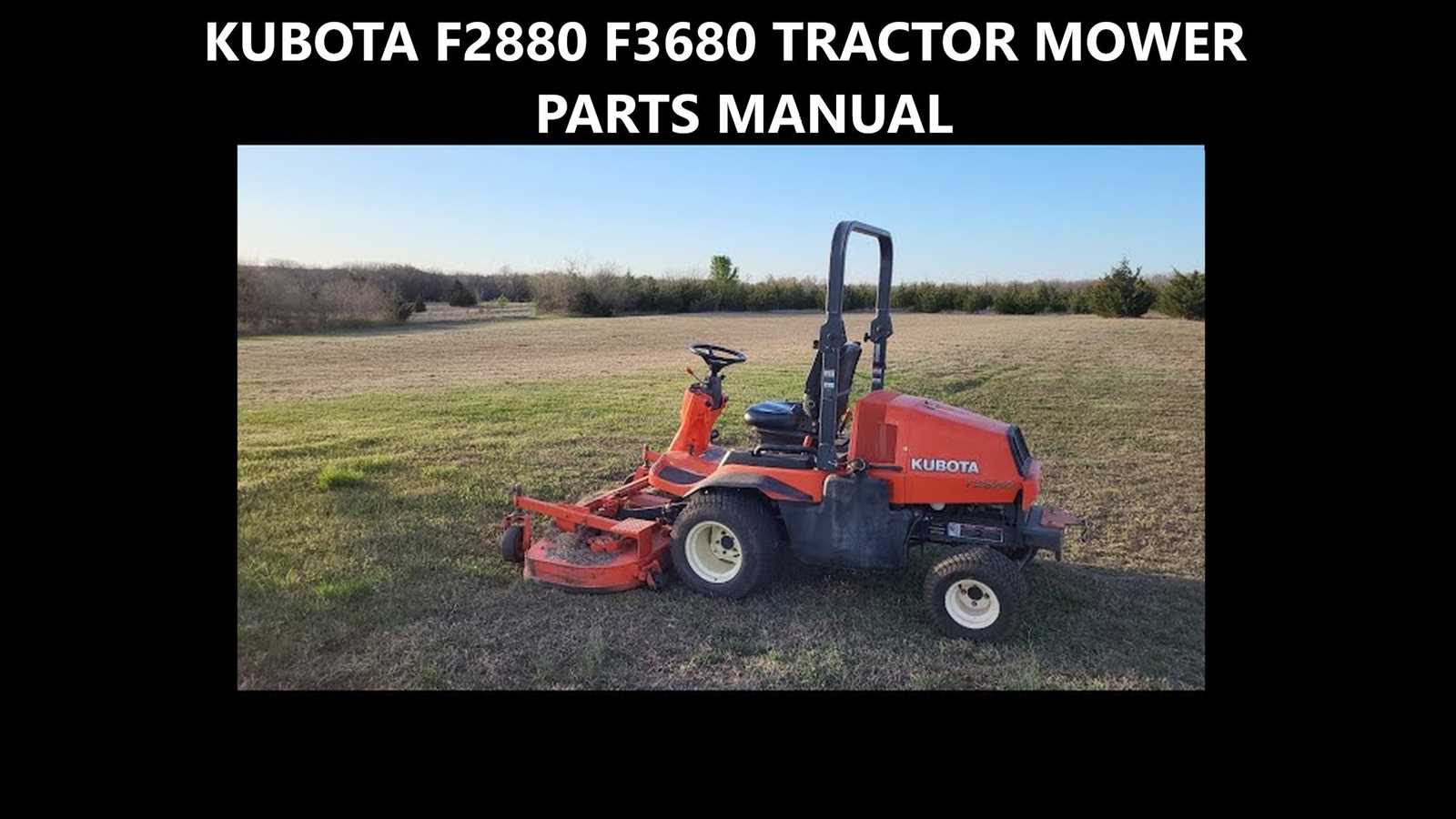
Regular upkeep of machinery is essential for optimal performance and longevity. Having access to appropriate maintenance sets and components is crucial for any operator looking to ensure their equipment runs smoothly. These kits typically include essential items needed for routine servicing, reducing downtime and enhancing overall efficiency.
Essential Maintenance Components
Every maintenance set should comprise critical elements that support the functionality of the equipment. Common inclusions are filters, lubricants, and seals, which work together to prevent wear and tear. Utilizing high-quality replacements helps maintain performance standards, ensuring that machinery operates without unnecessary interruptions.
Benefits of Using Quality Replacements
Investing in reliable components is beneficial in the long run. Quality replacements enhance durability, minimize the likelihood of malfunctions, and can lead to cost savings through improved efficiency. Choosing components that meet or exceed original specifications is a wise decision for maintaining the integrity of the equipment.
Tire Options and Wheel Assembly
When selecting the appropriate tires and wheel configuration for a compact agricultural vehicle, it is essential to consider various factors that influence performance and handling. Different tire types are designed to suit specific terrains and operational requirements, ensuring optimal traction and stability during use. Understanding the assembly components and their arrangement is also crucial for maintaining efficiency and safety.
Several tire choices are available, each tailored for distinct applications, such as turf-friendly designs for delicate ground surfaces or rugged patterns for rough terrains. Furthermore, the proper wheel assembly contributes significantly to the overall effectiveness of the vehicle, enhancing maneuverability and load-bearing capacity.
Tire Type Features Best Use Ag Tires Deep treads, excellent traction Agricultural fields, muddy conditions Industrial Tires Durable, resistant to wear Construction sites, rough surfaces Turf Tires Wide, low-profile design Lawns, soft ground All-Terrain Tires Versatile tread patterns Mixed environments, general use Proper installation and maintenance of the wheel assembly are vital to ensure the longevity and performance of the vehicle. Regular checks of tire pressure and alignment can prevent premature wear and enhance driving comfort. By carefully considering the tire options and assembly details, users can significantly improve their operational effectiveness.