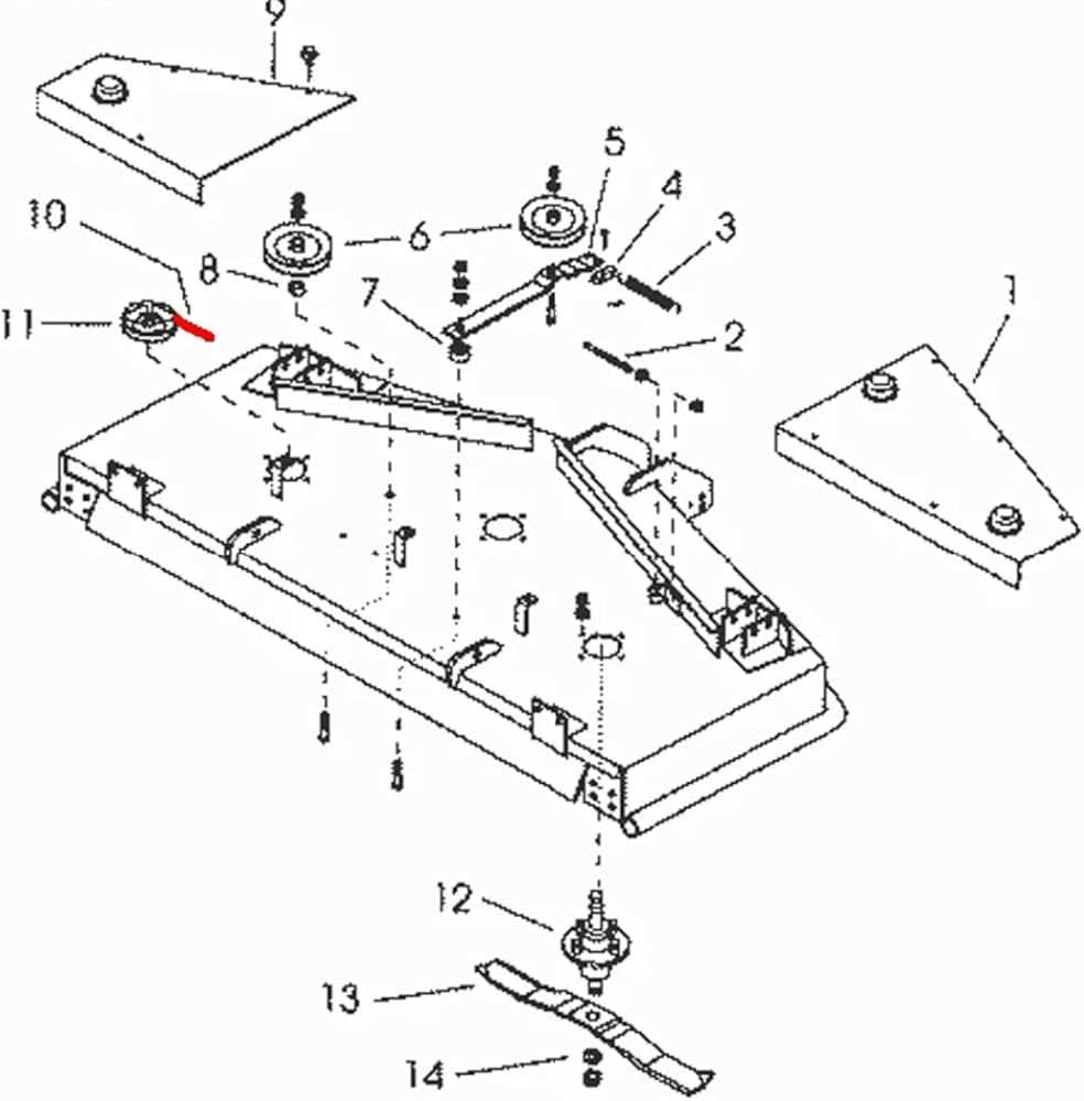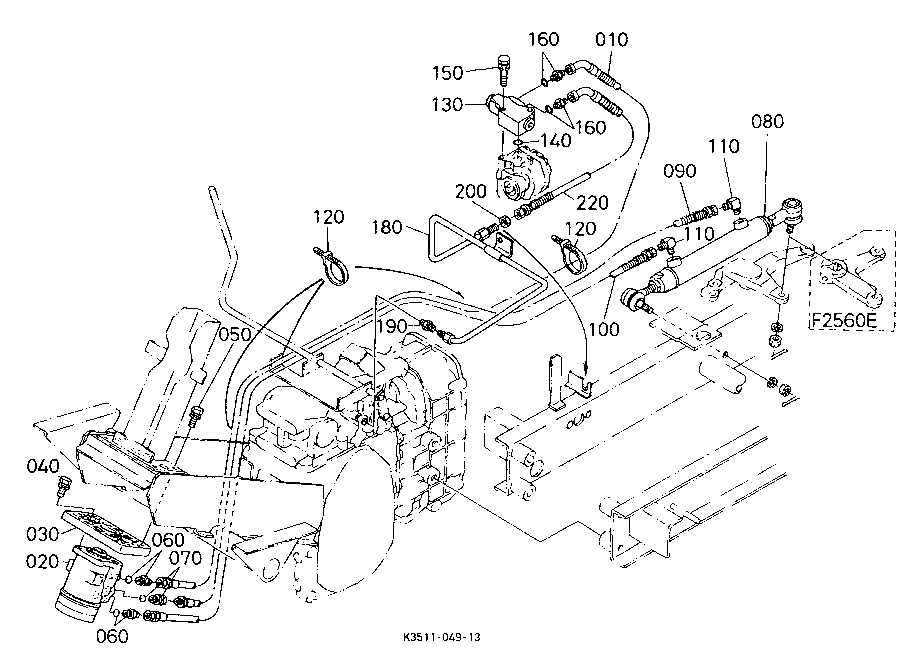
Understanding the layout of essential machine components is crucial for anyone looking to maintain or repair equipment. A clear and organized illustration of how various elements fit together helps in quickly identifying issues and ensuring smooth operation. Whether you’re dealing with an intricate engine or simpler mechanical structures, a well-designed schematic provides valuable insight.
Each mechanical system consists of interconnected parts that work in harmony. Having access to a detailed layout of these sections can simplify the process of troubleshooting and ensure efficient upkeep. By referring to the right visual guide, tasks such as assembly, replacement, or routine checks become significantly easier.
In this article, we will delve into the importance of these schematics and how they serve as an indispensable tool for both professionals and hobbyists alike. From core engine components to smaller mechanical parts, these diagrams help in streamlining the maintenance and repair process.
Component Layout Overview for a Versatile Lawn Tractor
This section presents a detailed look into the essential mechanical layout of a well-engineered mowing machine. Each section of this vehicle is designed to enhance performance, reliability, and ease of maintenance. By understanding how the various assemblies connect, users can ensure efficient operation and proper care of the equipment.
Main Mechanical Systems
The core mechanical systems include the driving mechanism, the cutting platform, and the hydraulic systems. These areas are meticulously crafted to provide smooth operation on varied terrains, ensuring optimal power transmission and precision in cutting.
Additional Structural Elements
Additional components such as the steering system, seating arrangement, and safety features are positioned strategically to offer both comfort and control. This thoughtful placement of elements ensures the operator can perform tasks with minimal strain and maximum safety.
Main Components of the Kubota F2560
The machinery consists of several essential elements that ensure its optimal performance and durability. Each part plays a crucial role in maintaining the efficiency and smooth operation of the equipment. Understanding the key components is vital for proper upkeep and troubleshooting.
At the core, the engine provides the power needed to drive the machine. The cutting system, designed for precision, ensures even and clean results during operation. Additionally, the hydraulic system allows for fluid movement and control of the various mechanisms, improving functionality and ease of use. Finally, the operator’s station is built for comfort and accessibility, allowing the user to easily manage the equipment’s controls.
Understanding the Engine Layout

Grasping the overall structure of the engine is essential for those looking to ensure efficient maintenance and repair. By understanding how various components interact within the system, one can gain insights into the machine’s operation and the best practices for keeping it in optimal condition.
Main Sections of the Engine
- Combustion Area – This is where the energy conversion takes place, turning fuel into power to drive the equipment.
- Cooling System – Ensures that the engine maintains a stable temperature during operation by regulating the heat generated during combustion.
- Lubrication System – Responsible for reducing friction between moving parts, prolonging the lifespan of internal components.
Key Components to Consider
- Wiring Harness: The backbone of the electrical setup, connecting various elements like lights, switches, and motors.
- Relays and Fuses: These protect the system from overloading and ensure the safe operation of electrical circuits.
- Battery and Charging System: The power source that drives the electrical components, along with the alternator to maintain energy flow.
- Ignition System: Powers the engine start-up and is connected to the safety features of the machine.
Hydraulic System Breakdown
The hydraulic system is essential for ensuring smooth operation of various mechanical functions. It plays a key role in transferring power through fluid dynamics, enabling efficient movement and control. This section will delve into the core components and operation of the system, explaining how fluid pressure is managed to drive different mechanisms.
Pumps and Fluid Flow: The system relies on a pump to create the necessary pressure, allowing the fluid to circulate. The pump ensures that the hydraulic fluid flows to the required parts of the system, maintaining optimal pressure levels for operation.
Valves and Control: Valves regulate the direction and amount of fluid flow, providing control over various functions. They are strategically placed to manage the system’s output and ensure precise movement and operation.
Cylinders and Actuators: Cylinders convert the fluid pressure into mechanical energy, driving movement in different components. Actuators further translate this energy into the desired actions, such as lifting or rotating.
Electrical Parts and Wiring Guide
Understanding the electrical system of a riding machine is essential for ensuring smooth operation and preventing issues. This guide provides a clear overview of key components and wiring connections, helping with maintenance and troubleshooting.
Each section of the wiring must be regularly inspected to prevent wear and ensure the reliable performance of the vehicle. Pay attention to connections and avoid loose or frayed wires that
Chassis and Frame Structure
The chassis and frame structure serves as the fundamental backbone of any machine, providing stability and support for various components. This robust assembly plays a crucial role in maintaining the overall integrity and performance of the equipment. Understanding its design and configuration is essential for effective maintenance and troubleshooting.
Design Features
The frame is engineered to withstand significant loads while ensuring durability in challenging environments. Its design incorporates strategic reinforcements to enhance strength and minimize flexing. Key elements include:
| Component | Description |
|---|---|
| Base Frame | The primary structure that supports all other components, ensuring stability. |
| Cross Members | Horizontal supports that distribute weight and add rigidity to the frame. |
| Mounting Brackets | Attachments that secure various elements, allowing for easy assembly and disassembly. |
Maintenance Considerations
Regular inspections and maintenance of the chassis are vital to ensure longevity and optimal performance. Check for signs of wear or corrosion, and address any issues promptly to prevent further damage. Proper maintenance will contribute to the reliability and efficiency of the overall system.
Transmission and Drivetrain Components
The efficiency of any agricultural machine relies heavily on its transmission and drivetrain systems. These components work in harmony to transfer power from the engine to the wheels, ensuring smooth operation across various terrains. Understanding the intricacies of these systems is essential for optimal performance and maintenance.
Key Elements of the System
At the heart of the drivetrain lies the gearbox, which plays a crucial role in adjusting speed and torque. Coupled with the driveshaft, it enables the transfer of power to the axles. The differential is another vital element, allowing for variations in wheel speed during turns, enhancing maneuverability.
Maintenance Considerations
Regular inspections of these components are vital for prolonging the lifespan of the machine. Checking fluid levels, examining for leaks, and ensuring that connections are secure can prevent costly repairs. By addressing minor issues promptly, operators can maintain the efficiency and reliability of the drivetrain system.
Fuel System Diagram and Parts
This section provides an overview of the components and layout of the fuel delivery system, highlighting its essential elements for optimal functionality. Understanding the configuration and individual components is crucial for effective maintenance and troubleshooting.
Key Components

The fuel delivery mechanism consists of several integral elements, each playing a vital role in ensuring the efficient flow of fuel to the engine. The primary components include the fuel tank, pump, filters, and injectors. These parts work together to maintain a steady supply of fuel, which is essential for optimal engine performance.
Component Overview
| Component | Description |
|---|---|
| Fuel Tank | Reservoir for storing fuel until needed by the engine. |
| Fuel Pump | Responsible for drawing fuel from the tank and delivering it to the engine. |
| Fuel Filter | Removes impurities and contaminants from the fuel before it reaches the engine. |
| Injectors | Spray a fine mist of fuel into the combustion chamber for efficient combustion. |
Cooling System Layout and Details

The cooling mechanism in machinery plays a crucial role in maintaining optimal operating temperatures. This section explores the configuration and components involved in this essential system, highlighting its design and functionality without delving into specific model references.
Components of the Cooling Mechanism
This system comprises several key elements that work together to ensure effective temperature regulation. Each part contributes to the overall efficiency and reliability of the equipment.
| Component | Function |
|---|---|
| Radiator | Disperses heat from the coolant to the air. |
| Water Pump | Circulates coolant throughout the engine. |
| Thermostat | Regulates coolant temperature by controlling flow. |
| Coolant Hoses | Transport coolant between the engine and radiator. |
Functionality and Efficiency
The effectiveness of the cooling system hinges on its ability to manage thermal energy. Proper maintenance and understanding of each component’s role enhance the longevity and performance of the entire apparatus, preventing overheating and related issues.
Steering Mechanism Overview
The steering mechanism plays a crucial role in ensuring precise control and maneuverability of the vehicle. This system is designed to translate the driver’s input into directional changes, enhancing the overall driving experience. Understanding its components and functionality is essential for effective maintenance and troubleshooting.
Key Components
Several critical elements work together to form the steering mechanism. Each component contributes to the overall performance and reliability of the system. Below is a summary of these key parts:
| Component | Description |
|---|---|
| Steering Wheel | The primary control interface for the operator, allowing for directional input. |
| Steering Column | Connects the steering wheel to the gear assembly, facilitating smooth movement. |
| Gear Assembly | Transforms the rotational motion from the steering wheel into lateral movement of the wheels. |
| Linkage System | Connects the gear assembly to the wheels, transmitting the steering force. |
Functionality and Maintenance
Regular inspection and maintenance of the steering system are vital to ensure safety and functionality. Keeping components in good condition helps prevent steering issues, which can lead to handling problems. Proper lubrication and timely replacement of worn parts can significantly extend the lifespan of the steering mechanism.
Maintenance Parts and Service Tips
Proper upkeep of your machinery is essential for ensuring optimal performance and longevity. This section focuses on key components and recommendations for servicing, aimed at enhancing efficiency and minimizing downtime.
Essential Components for Maintenance

Regular inspections and timely replacement of critical components can greatly affect the functionality of your equipment. Below are some vital elements to monitor:
| Component | Frequency of Inspection | Recommended Action |
|---|---|---|
| Filters | Every 50 hours of operation | Replace if dirty or clogged |
| Fluids | Every 100 hours of operation | Check levels and change as necessary |
| Belt Tension | Weekly | Adjust if loose or damaged |
| Blades | Every 20 hours of use | Sharpen or replace as needed |
Service Recommendations
To achieve optimal performance, it is advisable to follow a structured service routine. Regularly scheduled maintenance checks will help identify potential issues before they become significant problems.
Keep a log of maintenance activities, noting any changes made or parts replaced. This practice not only aids in tracking performance but also serves as a valuable reference for future servicing needs.