When working with small-scale construction machines, it’s essential to have a clear understanding of how their mechanisms are organized. The functionality of these machines relies on various interconnected systems that must work together efficiently. Each element plays a crucial role in ensuring smooth operation, durability, and the ability to handle tough tasks.
In this article, we will explore how different mechanical and hydraulic elements come together to create a reliable system. Knowing how these components interact is vital for anyone involved in maintaining or repairing such equipment. From the engine assembly to hydraulic systems, each section will be discussed to help you better understand how everything is structured.
By gaining insight into the configuration of these machines, you’ll be better equipped to troubleshoot issues and keep the machinery running efficiently. This knowledge is invaluable for ensuring long-term performance and minimizing downtime on any project.
Kubota KX161-3 Components Overview
The structural design of this advanced construction equipment is built for efficient performance. Each element within the machine is purposefully crafted to ensure both power and precision in a wide variety of tasks. In this section, we will explore the key mechanical components, offering insight into their functionality and contribution to overall operation.
Engine and Hydraulic System
The engine is the driving force behind the machine, providing the necessary energy for all functions. Connected to a robust hydraulic system, it allows for smooth, responsive movement of the arm, bucket, and attachments. The hydraulic system ensures that the equipment operates efficiently, delivering power exactly where it is needed.
Track and Undercarriage
The undercarriage is designed for stability and strength, supporting the weight and movement of the machine. Equipped with durable tracks, the machine is capable of navigating various terrains with ease. This ensures optimal traction and balance, enabling it to perform effectively in diverse environments.
Engine Assembly and Key Parts

The internal components of the engine are meticulously designed to ensure optimal performance. A detailed understanding of the various elements involved in the assembly helps in maintaining and troubleshooting the system efficiently. Below is an overview of the essential sections that make up the engine.
- Cylinder Block: This is the foundation, housing the pistons and serving as the backbone of the engine.
- Pistons: These move within the cylinders, driven by the combustion process, converting energy into motion.
- Crankshaft: Responsible for translating the linear movement of the pistons into rotational motion, driving the mechanical system.
- Camshaft: Controls the timing of the intake and exhaust valves, ensuring synchronization in the combustion cycle.
- Valves: These regulate the intake of air and fuel and the expulsion of exhaust gases from the cylinders.
- Connecting Rods: Connect the pist
Hydraulic System Breakdown
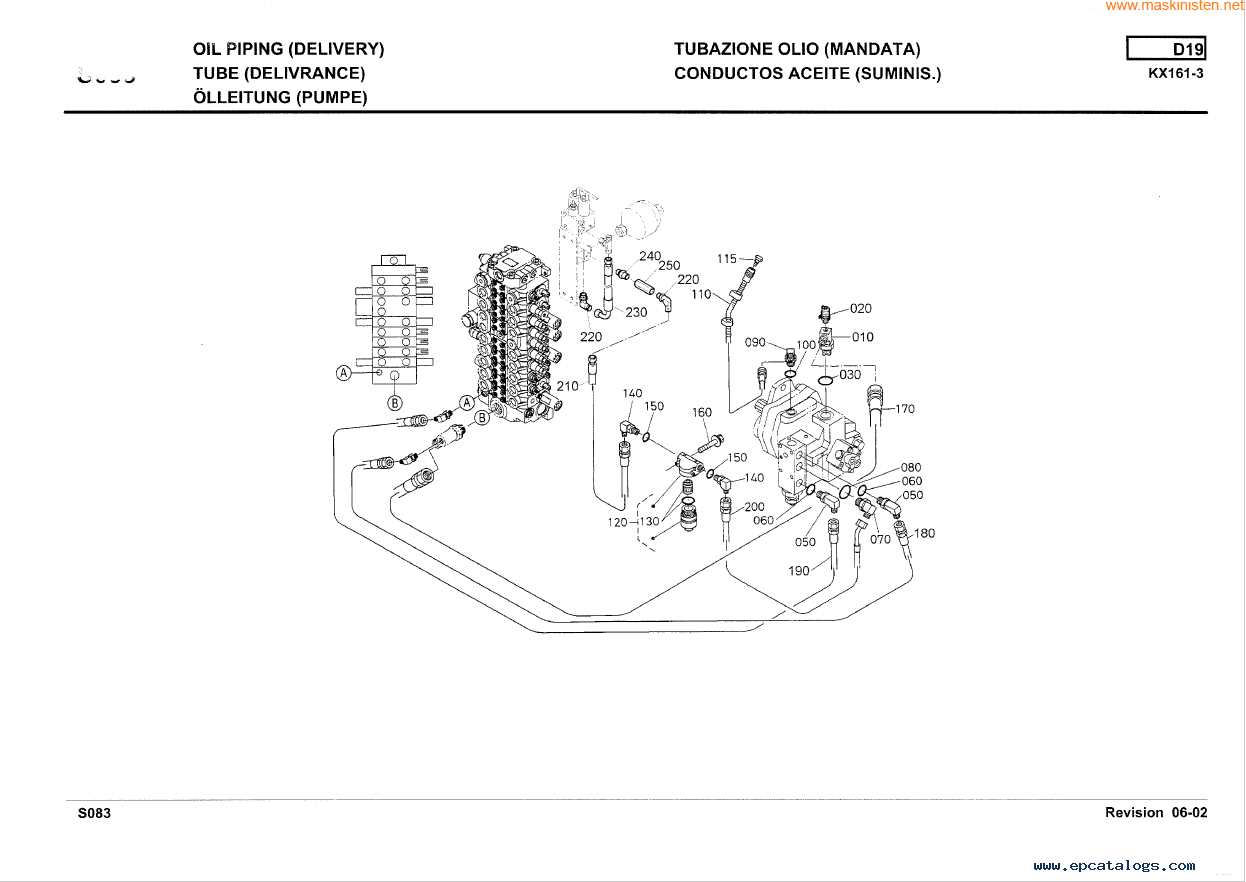
The hydraulic system is a crucial component in many heavy-duty machines, responsible for powering various mechanical operations. Understanding how this system works helps in maintaining its efficiency and ensuring smooth operations. This breakdown explores the fundamental aspects of how fluid dynamics are utilized to transmit force and control movement within the equipment.
The system primarily consists of pumps, cylinders, and valves, each playing a vital role. Pumps generate the necessary flow, cylinders convert fluid power into mechanical motion, and valves control the direction and pressure of the fluid. By regulating these elements effectively, the entire machine can perform a variety of tasks with precision.
It’s essential to ensure that the fluid levels and pressure are maintained within optimal ranges, as improper handling may lead to reduced performance or system failure. Routine inspection and timely replacements of worn-out components are key to preventing issues and prolonging the operational life of the hydraulic mechanism.
Undercarriage and Track System Layout
The undercarriage and track system form the foundation of any heavy machinery, ensuring stability and smooth movement over various terrains. This section provides an overview of the core components and structure that allow the machine to maintain balance and traction in challenging environments.
Tracks are essential for distributing the machine’s weight evenly, allowing it to travel across uneven or soft ground without sinking. The track shoes play a critical role in enhancing grip, offering increased traction, especially in muddy or loose conditions.
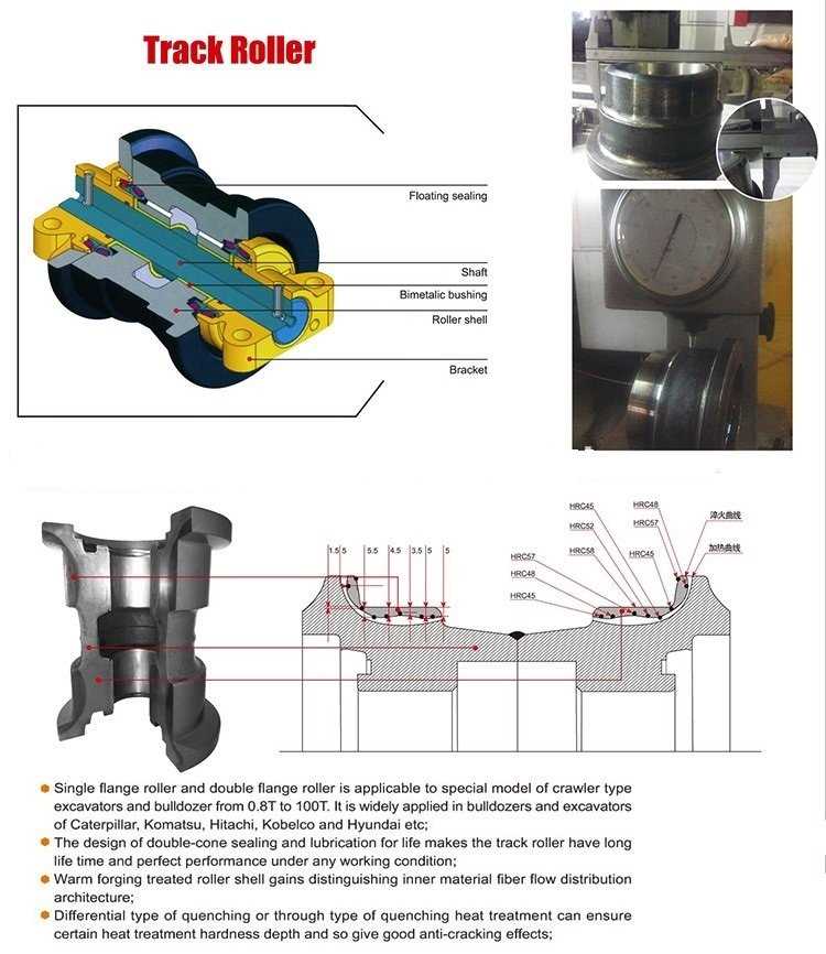
The rollers and idler wheels support the tracks, helping guide them and reduce friction during operation. These components ensure the tracks stay aligned and offer smooth motion. Maintaining proper tension in the track is crucial to avoid excessive wear and ensure efficiency.
Sprockets work in tandem with the tracks, engaging with the links to drive the system forward or backward. They are integral to the movement, providing the force required to navigate different terrains.
Finally, the frame supports the entire system, providing a stable base for all these elements to function cohesively. A
Control Panel and Dashboard Elements

The control panel and dashboard are key components for managing and monitoring the machine’s various functions. These elements provide the operator with critical information and control options for smooth operation and efficiency. Understanding the layout and functions of the buttons, switches, and displays is essential for optimal performance and safety.
Main Controls
The primary controls on the dashboard allow the user to start, stop, and adjust the system’s functions. Ignition switches, throttle controls, and mode selectors are typically located for easy access. The arrangement of these controls is designed to ensure quick and efficient operation.
Monitoring Indicators
Several indicators and gauges provide real-time data regarding the machine’s performance. Fuel level, temperature, and engine status are commonly displayed. These visual signals help the operator to promptly respond to any issues, preventing damage or downtime.
Excavator Arm and Boom Components
The arm and boom assembly of an excavating machine is crucial for its operational efficiency. These elements work in unison to perform a variety of tasks, including digging, lifting, and moving materials. Understanding the various components within this assembly is essential for effective maintenance and operation.
Component Description Boom The primary structure that connects to the main body of the excavating machine, providing reach and height for various tasks. Arm An extension of the boom that allows for greater flexibility and reach during operations, enabling the machine to maneuver around obstacles. Bucket The attachment at the end of the arm, designed for scooping and transporting materials, varying in size and shape depending on the job. Hydraulic Cylinders These components provide the necessary force to extend and retract the arm and boom, using hydraulic fluid to create movement. Linkage System A series of joints and connectors that allow for the controlled movement of the arm and boom, ensuring precision and stability during operation. Regular inspection and maintenance of these components are vital to ensure the reliability and longevity of the excavating machine. Understanding their functions can help operators identify potential issues early, reducing downtime and repair costs.
Cooling System Diagram
The cooling system is essential for maintaining optimal operating temperatures in machinery. Its design ensures that the engine remains within a safe temperature range, preventing overheating and enhancing overall efficiency. Understanding the components and their interconnections can help in troubleshooting issues and ensuring proper maintenance.
Key Components
- Radiator: Dissipates heat from the coolant.
- Water Pump: Circulates coolant throughout the system.
- Thermostat: Regulates coolant flow based on temperature.
- Coolant Reservoir: Holds excess coolant and allows for expansion.
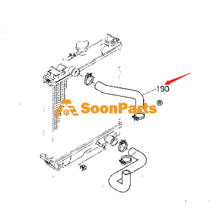
- Hoses: Facilitate the movement of coolant between components.
Operation Process
- The water pump draws coolant from the reservoir and circulates it through the engine.
- As the engine operates, it generates heat, which is absorbed by the circulating coolant.
- The heated coolant flows to the radiator, where it releases heat into the air.
- The thermostat monitors the temperature and adjusts coolant flow to maintain optimal engine temperature.
- Excess coolant returns to the reservoir for reuse in the system.
Fuel System and Connections
The fuel system is a vital component of any machinery, responsible for delivering the necessary energy to the engine. This system consists of various elements that work in unison to ensure optimal performance and efficiency. Understanding these components and their connections is essential for maintenance and troubleshooting.
Key elements of the fuel system include:
- Fuel Tank: Stores the fuel, ensuring a sufficient supply for operation.
- Fuel Pump: Transfers fuel from the tank to the engine, maintaining adequate pressure.
- Fuel Filter: Cleans the fuel by removing impurities, preventing damage to the engine.
- Fuel Injector: Delivers the precise amount of fuel into the combustion chamber for efficient burning.
- Fuel Lines: Transport fuel between various components, designed to withstand high pressures.
Connections within the fuel system are crucial for seamless operation. Proper alignment and secure fittings are necessary to avoid leaks and ensure efficient fuel flow. Regular inspections and maintenance can prevent potential issues that may arise due to wear and tear or environmental factors.
In summary, a well-functioning fuel system is integral to the performance of machinery. Familiarity with its components and connections enhances reliability and longevity, making it essential for any operator or technician.
Electrical Wiring and Fuse Box
The electrical system in machinery plays a crucial role in ensuring optimal performance and reliability. Understanding the wiring layout and the fuse arrangement is essential for troubleshooting issues and maintaining functionality. This section provides insights into the structure and significance of the electrical components that facilitate seamless operation.
Wiring serves as the backbone of any electronic setup, connecting various components such as switches, sensors, and motors. Proper wiring ensures that electrical signals flow smoothly, preventing malfunctions. It is vital to regularly inspect the wiring for signs of wear or damage, as faulty connections can lead to operational failures.
The fuse box acts as a protective element within the electrical system, safeguarding components from overloads and short circuits. Each fuse is designated for specific circuits, and understanding their configuration helps in quickly identifying problems. Regularly checking and replacing blown fuses is an important maintenance task that contributes to the longevity of the equipment.
By familiarizing oneself with the wiring setup and fuse layout, operators can effectively manage electrical issues, ensuring that machinery operates efficiently and safely. Knowledge of these systems empowers users to perform basic troubleshooting and maintain optimal functionality.
Cabin Interior Parts Layout

The arrangement of components within the operator’s compartment plays a crucial role in enhancing comfort and usability. A well-organized interior ensures that all necessary controls and instruments are easily accessible, thereby improving efficiency during operation. This layout not only affects the operator’s experience but also contributes to the overall functionality of the machinery.
Component Description Control Panel Centralized interface for managing machine functions and monitoring status indicators. Seat Ergonomically designed for comfort during extended use, often adjustable for optimal positioning. Dashboard Displays essential information such as fuel levels, temperature, and operational hours. Storage Compartments Provides space for tools and personal items, helping to keep the cabin organized. Controls Levers and pedals strategically placed for intuitive operation and ease of access. Windows Designed for visibility and safety, with options for opening or closing as needed. Climate Control System that regulates temperature and airflow to enhance the comfort of the operator. Drive Motor and Transmission Components
The drive motor and transmission assembly is crucial for the efficient operation of heavy machinery. This system is responsible for converting electrical energy into mechanical energy, enabling movement and power transfer within the equipment. Understanding the various elements involved can help in diagnosing issues and ensuring optimal performance.
Key Elements of the Drive Motor
The drive motor typically consists of several components, including the rotor, stator, and housing. The rotor is the rotating part that generates torque, while the stator provides the necessary magnetic field. Proper maintenance of these elements is essential for preventing overheating and ensuring longevity. Regular inspections can help identify wear and tear that may lead to performance issues.
Transmission System Overview
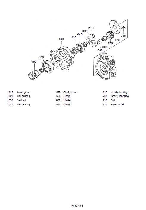
The transmission system includes gears, shafts, and clutches that work together to control the speed and torque delivered to the wheels. The gearbox plays a significant role in this process, enabling the operator to adjust the power output according to the operational demands. Understanding the relationship between these components is vital for effective troubleshooting and maintenance.
Loader and Attachments Diagram
This section provides an overview of the components associated with loaders and their various attachments. Understanding the layout and functionality of these elements is essential for effective operation and maintenance. Each component plays a crucial role in enhancing the versatility and efficiency of the machinery.
Key Components of Loaders
Loaders typically consist of several main components that contribute to their performance. The primary parts include the lifting arm, bucket, and attachment mechanisms. The lifting arm is designed to raise and lower the bucket, allowing for the handling of materials. The bucket serves as the main tool for scooping, lifting, and transporting various substances, while the attachment mechanisms enable the quick swapping of different implements to suit specific tasks.
Popular Attachments and Their Uses
Various attachments can be utilized with loaders to perform a wide range of functions. Common examples include forks for pallet handling, snow plows for clearing, and grapples for handling bulk materials. Each attachment is tailored for specific tasks, providing enhanced functionality and efficiency. By selecting the appropriate implement, operators can maximize productivity and achieve optimal results in their projects.
Maintenance Points and Service Areas
Regular upkeep and attentive servicing are crucial for ensuring the longevity and optimal performance of any machinery. This section outlines essential maintenance tasks and key service locations that should be prioritized during routine checks and repairs.
Below are critical areas to focus on during maintenance:
- Fluid Levels: Check and maintain appropriate levels of hydraulic fluid, engine oil, and coolant.
- Filters: Regularly inspect and replace air and oil filters to ensure efficient operation.
- Batteries: Monitor battery connections and charge levels; clean terminals to prevent corrosion.
- Belts and Hoses: Examine belts for wear and tension; inspect hoses for leaks or damage.
Furthermore, consider the following service tasks:
- Conduct a thorough inspection of the undercarriage for wear and tear.
- Lubricate pivot points and moving parts to minimize friction.
- Test the electrical systems, including lights and controls, to ensure proper functionality.
- Evaluate tire condition and pressure; replace or inflate as necessary.
Adhering to these maintenance points and service areas will enhance the efficiency and reliability of the machinery, leading to reduced downtime and increased productivity.