Cooling System Check
Transmission System and Its Functions
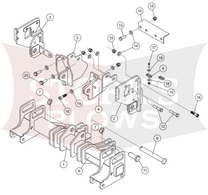
The transmission system plays a crucial role in the operation of any machine, serving as a bridge between the engine and the wheels. It is responsible for managing the power generated by the engine, ensuring that it is delivered smoothly and efficiently to drive the machine forward or backward. This system enables different speed ranges, allowing the machine to adapt to various conditions, whether it requires higher speed or greater torque.
By regulating the distribution of energy, the transmission ensures optimal performance and prevents damage to other components. Without it, controlling the speed and direction of movement would be impossible, as it allows for precise adjustments and smooth transitions during operation. The transmission system’s key purpose is to enhance efficiency and ensure the longevity of the overall mechanism.
Critical Transmission Components Overview
The efficiency and reliability of a vehicle’s drivetrain are heavily dependent on its essential components. Understanding these elements is crucial for proper maintenance and functionality. This section explores the vital elements within the transmission system that contribute to optimal performance, focusing on their roles and interactions.
Key Elements in the Drivetrain
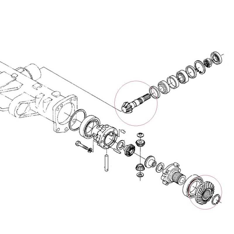
Among the most significant components are the gears and shafts, which facilitate the transfer of power from the engine to the wheels. Gears are designed to adjust speed and torque, enabling smooth acceleration and deceleration. Additionally, the gearbox plays a pivotal role in selecting the appropriate gear ratio, impacting the overall driving experience.
Fluid Dynamics and Performance
The fluid used in the transmission system is equally important. Transmission fluid serves multiple functions, including lubrication, cooling, and hydraulic power transmission. Maintaining proper fluid levels and quality is essential to ensure that all components function harmoniously, minimizing wear and preventing potential failures.
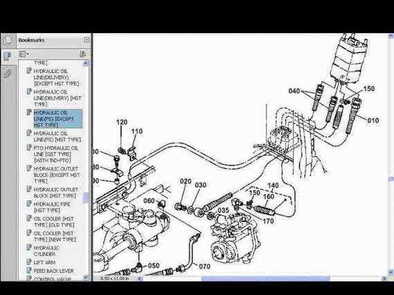
Hydraulic System Explained for Kubota L4060
The hydraulic system is a vital component in modern agricultural machinery, enabling efficient operation and enhanced performance. This system utilizes fluid pressure to transfer power, making it essential for various functions, from lifting implements to steering control. Understanding the intricacies of this system can significantly improve maintenance practices and operational efficiency.
Components of the Hydraulic System
The hydraulic system comprises several key elements that work together to ensure optimal performance. Each part plays a specific role in the overall functionality, contributing to the effective movement and control of machinery.
| Component |
Function |
| Hydraulic Pump |
Generates fluid pressure needed for system operation. |
| Hydraulic Fluid |
Transmits power and lubricates components. |
| Control Valves |
Regulate fluid flow and pressure to various functions. |
| Actuators |
Convert hydraulic energy into mechanical movement. |
Maintenance Tips for Optimal Performance
Regular maintenance of the hydraulic system is crucial for ensuring longevity and reliability. Keeping the hydraulic fluid clean, checking for leaks, and inspecting components periodically can prevent costly repairs and downtime. Proper care of this system not only enhances performance but also contributes to the overall efficiency of the machinery.
How the Hydraulic System Powers the Tractor
The hydraulic mechanism serves as a crucial component in the functionality of agricultural machinery, enabling efficient operation of various implements and systems. By utilizing fluid pressure, this system transforms energy into powerful movements, essential for performing heavy tasks in the field.
This hydraulic arrangement typically consists of several key elements:
- Fluid Reservoir: Stores hydraulic fluid necessary for the system’s operation.
- Pump: Converts mechanical energy into hydraulic energy, creating the pressure needed to move fluid through the system.
- Control Valves: Regulate the flow and direction of hydraulic fluid, allowing operators to manage different functions.
- Cylinders: Actuate movements by converting hydraulic pressure into linear motion, enabling the lift and tilt of implements.
- Hoses and Fittings: Connect various components, ensuring efficient fluid transfer throughout the system.
When the pump operates, it draws fluid from the reservoir and sends it under pressure to the control valves. Operators can then manipulate these valves to direct the flow to specific cylinders, facilitating actions such as raising, lowering, or tilting equipment attached to the tractor.
The efficiency of this system not only enhances productivity but also reduces the physical effort required by operators. Understanding how hydraulic principles function within this machinery can significantly improve its utilization and maintenance.
Electrical System Components and Layout
The electrical framework of modern agricultural machinery plays a crucial role in ensuring efficient operation and performance. This section delves into the various elements that make up the electrical network, highlighting their functions and arrangement within the overall system. A clear understanding of these components is essential for effective troubleshooting and maintenance.
| Component |
Description |
Function |
| Battery |
Stores electrical energy for starting the engine and powering accessories. |
Provides the initial power needed to crank the engine and operates electrical devices. |
| Alternator |
Generates electricity while the engine is running. |
Charges the battery and powers the electrical system during operation. |
| Starter Motor |
Engages with the engine to initiate the combustion process. |
Turns the engine over to start it when the ignition is activated. |
| Fuses |
Protects electrical circuits from overloads. |
Disconnects the circuit when excessive current flows, preventing damage. |
| Wiring Harness |
Connects all electrical components together. |
Facilitates the flow of electricity and signals throughout the system. |
| Relays |
Electromechanical switches that control high-current circuits. |
Allows low-current signals to control high-current devices safely. |
| Ignition System |
Ignites the fuel-air mixture in the engine cylinders. |
Ensures the engine operates smoothly by providing the necessary spark. |
Understanding the layout and interconnections of these components is vital for any technician or operator. A well-organized electrical system not only enhances reliability but also simplifies troubleshooting processes, making it easier to identify and rectify issues as they arise.
Understanding the Electrical Wiring
The electrical system in machinery plays a crucial role in its overall functionality. A comprehensive grasp of how various components are interconnected helps in troubleshooting and maintenance. Proper understanding of these connections ensures optimal performance and longevity of the equipment.
Key Components of the Electrical System
Central to the electrical network are the battery, alternator, and various switches. The battery supplies power, while the alternator recharges it during operation. Switches act as control points, enabling users to manage different functionalities seamlessly.
Importance of Proper Connections
Ensuring secure and accurate connections within the electrical system is vital. Loose or damaged wires can lead to operational failures or safety hazards. Regular inspections can help identify potential issues early, allowing for timely repairs.
Front Axle and Steering Mechanism Details
The front axle and steering system play a crucial role in the overall functionality and maneuverability of the machinery. These components are designed to support the weight of the vehicle while allowing for smooth directional changes. Understanding their intricacies can aid in maintenance and troubleshooting.
Key components of the front axle assembly include:
- Spindles: These support the wheel hubs and facilitate rotation.
- Kingpins: Central pivots that allow the wheels to turn in relation to the chassis.
- A-frames: Structural elements that connect the wheels to the vehicle, providing stability.
- Bearings: Reduce friction between moving parts, ensuring smooth operation.
- Suspension links: Connect the axle to the vehicle’s frame, absorbing shocks during operation.
The steering mechanism comprises various components that work together to provide accurate control:
- Steering wheel: The primary input device for directing the vehicle.
- Steering column: Connects the steering wheel to the gearbox.
- Steering gearbox: Converts the rotational motion of the wheel into lateral movement of the wheels.
- Linkages: Transfer movement from the gearbox to the wheels, ensuring responsive handling.
Regular inspection and maintenance of these components are essential for optimal performance and longevity. Any signs of wear or damage should be addressed promptly to avoid potential issues during operation.
Parts Involved in Kubota Steering System
The steering mechanism of a compact utility vehicle is essential for ensuring precise handling and maneuverability. This system comprises several crucial components that work together to facilitate smooth and responsive steering actions.
Steering Wheel: The primary interface for the operator, the steering wheel transmits the driver’s input to the steering assembly.
Steering Column: This structure connects the steering wheel to the rest of the system, providing stability and housing various controls.
Steering Gear: A key element that converts the rotational motion of the steering wheel into lateral movement of the front wheels, enabling directional changes.
Pitman Arm: This component links the steering gear to the steering linkage, facilitating the transfer of motion.
Idler Arm: This part supports the steering linkage, maintaining the proper alignment and function of the system.
Drag Link: Serving as a connection between the pitman arm and the steering knuckles, the drag link plays a vital role in transmitting motion.
Steering Knuckles: These components allow the wheels to pivot, ensuring smooth turns while maintaining stability.
Power Steering Pump: This hydraulic pump enhances steering ease, providing additional assistance when maneuvering, particularly at low speeds.
Hydraulic Fluid Reservoir: This container holds the fluid necessary for the hydraulic system to function effectively, ensuring optimal performance.
Understanding these elements and their roles is vital for maintaining the steering functionality of the vehicle, ensuring safe and efficient operation on various terrains.
Cooling System Components and Operation
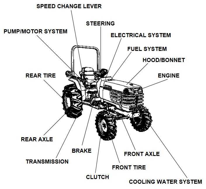
The efficiency of an engine relies heavily on its ability to maintain optimal temperatures, preventing overheating and ensuring smooth operation. The cooling system plays a vital role in this process, utilizing various components to regulate temperature and maintain performance. Understanding how these elements function together can provide insights into the overall health of the engine and its operational efficiency.
Main Components of the Cooling System
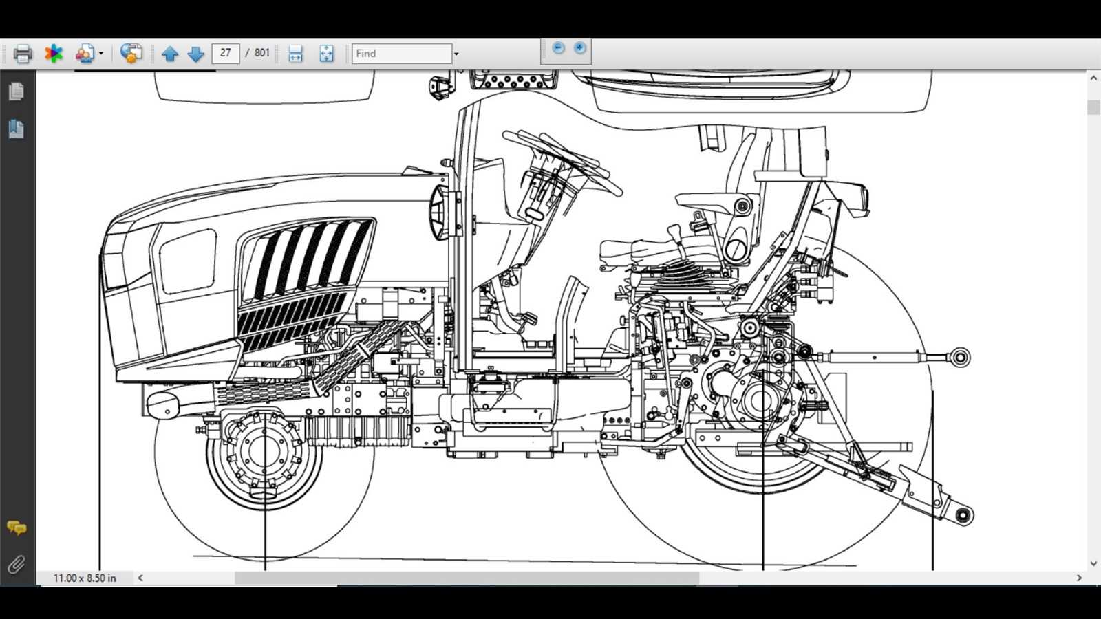
At the core of the cooling mechanism are essential components that work in harmony. The radiator serves as a heat exchanger, dissipating excess heat from the coolant, while the water pump circulates this fluid throughout the engine. Thermostats monitor temperature levels, allowing the system to maintain a consistent operating range. Additionally, hoses and coolant reservoirs play crucial roles in transporting the fluid and ensuring proper pressure levels within the system.
Operational Principles
The cooling system operates on a closed loop principle, where the coolant absorbs heat from the engine and releases it through the radiator. As the engine heats up, the thermostat opens, allowing the coolant to flow into the radiator, where air circulation cools it down. This cycle continues as long as the engine is running, ensuring that the temperature remains within a safe range. Regular maintenance of these components is essential for preventing overheating and ensuring long-term reliability.
|
