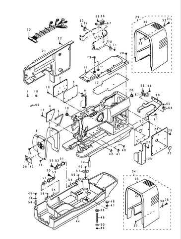
The intricate world of engineering often relies on visual representations to convey complex relationships and functionalities. These illustrations serve as essential tools for both learning and communication, enabling professionals and enthusiasts alike to grasp the underlying mechanisms of various systems.
By examining these visuals, one can uncover the ultimate interactions between components, revealing how each element contributes to the overall operation. Such insights not only enhance comprehension but also facilitate problem-solving and innovation in design.
As we delve deeper into this topic, we will explore different types of representations, their significance in the engineering field, and how they can aid in understanding the dynamics at play in mechanical systems.
Understanding Machine Parts Diagrams
Grasping the visual representations of components within complex systems is essential for efficient operation and maintenance. These illustrations serve as vital tools for comprehending the relationships and functions of various elements in engineering and technology. By examining these schematics, one can gain insights into assembly, troubleshooting, and overall functionality.
| Element | Description |
|---|---|
| Component A | Main functionality provider, often central to operations. |
| Connector B | Facilitates interaction between multiple elements. |
| Support Structure C | Ensures stability and proper alignment of various units. |
Importance of Accurate Diagrams
Precision in visual representations is crucial for effective communication within any technical field. These illustrations serve as foundational tools that facilitate understanding and maintenance, ensuring that complex systems are manageable and operable.
Clarity and Understanding
Clear visuals enhance comprehension and reduce the likelihood of errors. When well-structured, they allow individuals to:
- Quickly identify components
- Understand relationships between elements
- Visualize assembly processes
Efficiency and Safety
Accurate representations contribute to both efficiency and safety in operations. Key benefits include:
- Streamlined troubleshooting and repairs
- Reduced training time for new personnel
- Minimized risk of accidents through better understanding
Common Symbols in Technical Drawings
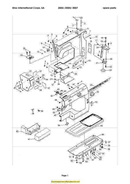
In the realm of technical illustrations, a universal language is essential for clear communication. Symbols serve as concise representations of complex ideas, enabling engineers, designers, and technicians to convey intricate information efficiently. Understanding these symbols is crucial for interpreting schematics accurately and ensuring that all stakeholders share a common understanding.
Types of Symbols
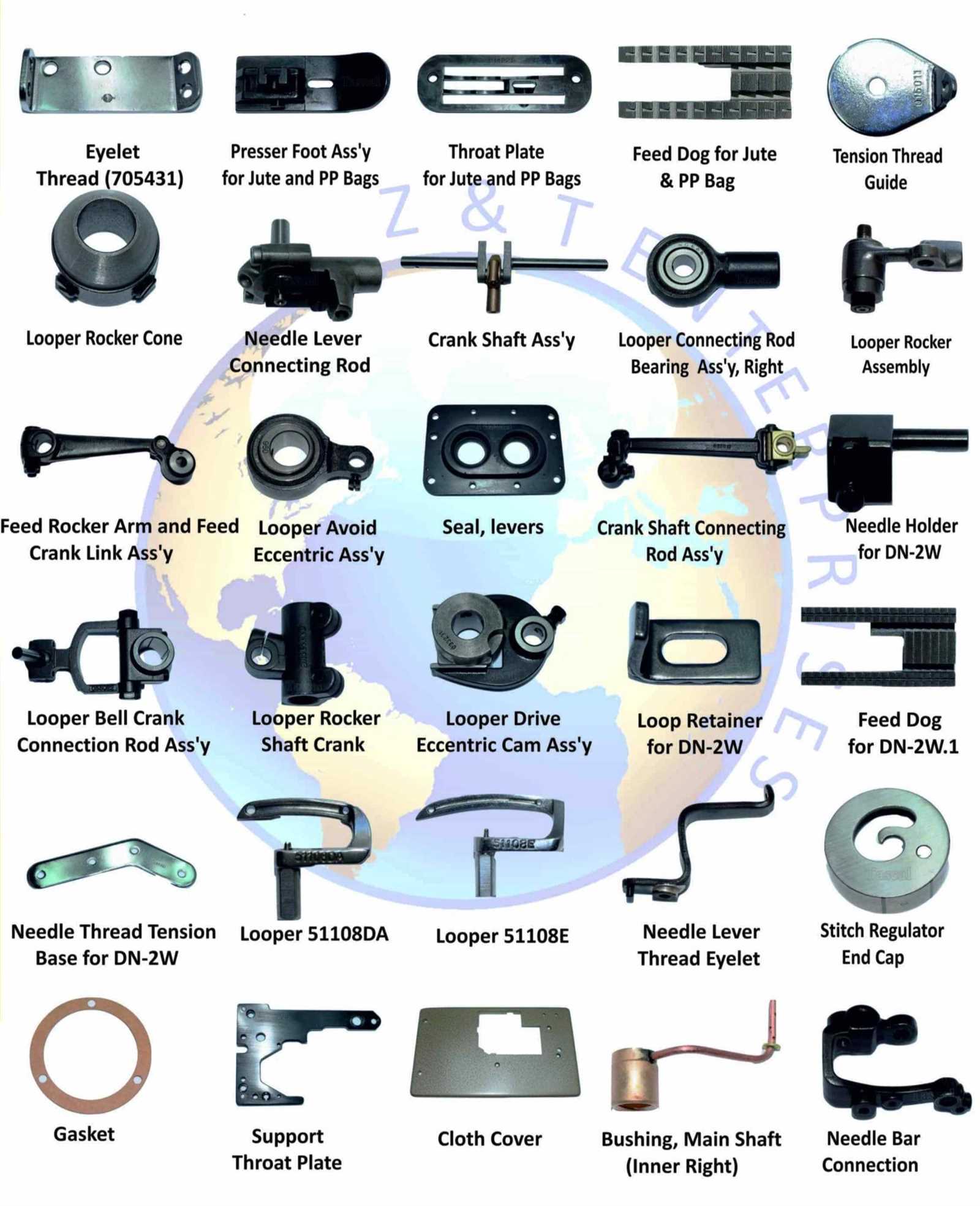
There are several categories of symbols commonly used in technical illustrations, each serving a specific purpose:
- Geometric Shapes: Represent basic forms such as circles, squares, and triangles, often indicating specific components or areas of interest.
- Lines: Different line styles (solid, dashed, dotted) denote various types of relationships or characteristics, such as visibility or boundaries.
- Textual Annotations: Labels or notes that provide additional context, specifications, or instructions related to the elements depicted.
Understanding Symbol Meaning
Familiarity with common symbols enhances the ability to read and interpret technical illustrations. Here are some widely recognized symbols and their meanings:
- Dimension Lines: Indicate measurements and sizes of components.
- Center Lines: Show the axis of symmetry for circular or cylindrical objects.
- Hatching: Represents different materials or finishes within a section view.
Mastering these symbols is not only essential for accurate interpretation but also for effective communication within multidisciplinary teams. By using these standardized representations, professionals can minimize misunderstandings and streamline collaboration.
Types of Machine Parts Illustrations
Illustrations serve as essential tools for understanding complex mechanisms and their components. These visual representations can vary significantly, each offering unique insights into the structure and functionality of various elements within a system. By utilizing different styles and approaches, these depictions enhance comprehension and facilitate effective communication among engineers and technicians.
Technical Drawings
Technical drawings are precise representations that include detailed specifications and measurements. They are often utilized in design and manufacturing processes, providing clear guidelines for assembly and maintenance. These illustrations focus on accuracy and clarity, ensuring that every element is depicted with exact proportions and annotations.
Exploded Views
Exploded views present a three-dimensional perspective, showcasing the arrangement of individual components in relation to one another. This style effectively highlights how each piece interacts within the whole system, making it easier to identify potential issues during assembly or disassembly. The visual separation of elements allows for a more intuitive understanding of their functions and interconnections.
Tools for Creating Diagrams
In the realm of visual representation, having the right tools can significantly enhance the clarity and effectiveness of your presentations. Various software solutions and applications provide users with the ability to design intricate illustrations, allowing for better communication of complex ideas. These tools cater to different needs, from simple sketches to comprehensive blueprints, making them indispensable for professionals and enthusiasts alike.
Types of Software
There are numerous types of software available for crafting visual representations. Some programs focus on vector graphics, offering flexibility and precision in creating detailed images. Others prioritize ease of use, featuring drag-and-drop interfaces that simplify the design process. Additionally, cloud-based platforms facilitate collaboration, enabling multiple users to contribute to a project in real-time.
Key Features to Consider
When selecting a tool for your visualization needs, consider features such as template availability, which can save time and inspire creativity. Look for options that provide export capabilities in various formats, ensuring compatibility with different applications. Furthermore, robust customization options allow for personalization, making your illustrations unique and tailored to your audience.
Reading and Interpreting Diagrams
Understanding visual representations of complex systems is essential for effective analysis and communication in various fields. These graphical illustrations serve as crucial tools, allowing individuals to grasp the relationships and functions within a given assembly. Mastering the skill of interpreting these visuals enables professionals to streamline processes, troubleshoot issues, and enhance overall productivity.
Key Elements to Consider
When examining a visual representation, it is important to pay attention to several key components. Recognizing symbols, lines, and annotations helps in deciphering the intended meaning and functionality depicted. Here are some fundamental aspects to focus on:
| Element | Description |
|---|---|
| Symbols | Represent different components or functions within the system. |
| Lines | Indicate connections, flows, or relationships between elements. |
| Annotations | Provide additional information or clarification regarding specific elements. |
Practical Tips for Effective Interpretation
To improve your ability to decode these visuals, consider the following strategies:
- Familiarize yourself with common symbols and their meanings.
- Practice identifying the flow of information or processes depicted.
- Consult accompanying documentation for context and explanations.
By honing these skills, you will enhance your comprehension and effectively utilize visual representations in your work.
Applications in Engineering and Manufacturing
The utilization of schematics in technical fields plays a pivotal role in optimizing design processes and enhancing productivity. These visual representations facilitate a clearer understanding of complex systems, enabling engineers and manufacturers to innovate and refine their approaches effectively.
Enhancing Design Efficiency
Through detailed visual layouts, professionals can explore various configurations and functionalities, leading to improved design cycles. Such clarity allows teams to identify potential issues early, thereby reducing time and resources spent on revisions.
Streamlining Production Processes
In manufacturing, these illustrations serve as crucial references, guiding the assembly and quality assurance processes. By providing clear instructions, they minimize errors and enhance overall operational efficiency, ultimately contributing to superior product quality.
Digital vs. Hand-Drawn Diagrams
The choice between digital and hand-crafted visuals can significantly influence clarity and communication. Each method presents distinct advantages and challenges that cater to different preferences and project needs.
- Precision: Digital illustrations often provide greater accuracy and neatness.
- Flexibility: Hand-drawn visuals allow for spontaneous creativity and unique expressions.
- Accessibility: Digital tools can facilitate easier sharing and editing among teams.
- Personal Touch: Hand-created images can convey a sense of authenticity and craftsmanship.
Ultimately, the decision hinges on the specific requirements of the task at hand, as well as the desired aesthetic and functional qualities.
Case Studies of Effective Diagrams
This section explores various examples that illustrate the power of visual representations in enhancing understanding and communication. By examining specific cases, we can uncover the ultimate strategies that lead to clarity and efficiency in complex systems.
Case Study 1: Automotive Assembly
In the automotive industry, visual representations have proven essential for streamlining assembly processes. Here are key insights:
- Utilization of clear visuals reduces assembly time by 20%.
- Color-coded elements help workers identify components quickly.
- Enhanced training materials improve onboarding efficiency.
Case Study 2: Aerospace Engineering
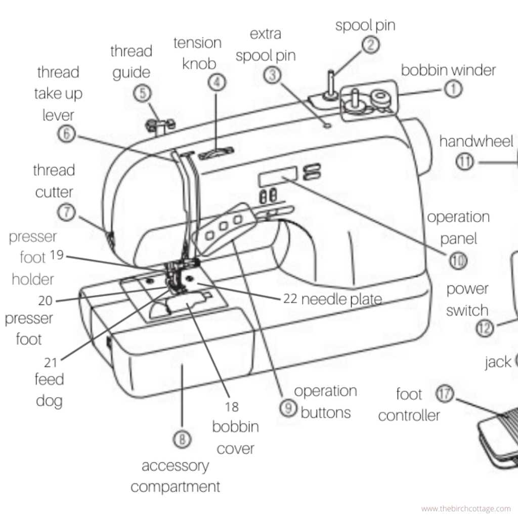
Aerospace engineering relies on detailed visuals to communicate intricate designs. Key takeaways include:
- Three-dimensional models facilitate better spatial understanding.
- Interactive visuals allow for real-time modifications and assessments.
- Standardized symbols promote consistency across documentation.
Tips for Clear Diagram Design
Creating effective visual representations requires attention to clarity and simplicity. A well-designed illustration conveys information efficiently, ensuring the audience grasps complex concepts effortlessly. Here are essential strategies to enhance the clarity of your visuals.
Use Consistent Symbols
Consistency in symbols and shapes helps viewers understand the relationships and functions within the illustration. Establish a key for any icons used, and stick to it throughout the visual.
Keep It Simple
Avoid clutter by limiting the number of elements. Focus on the essential components to convey your message without overwhelming the viewer. This makes interpretation straightforward.
| Tip | Description |
|---|---|
| Limit Colors | Use a maximum of three colors to maintain focus. |
| Label Clearly | Ensure all components are labeled succinctly for easy identification. |
| Maintain Scale | Keep proportions consistent to represent real-life dimensions accurately. |
Standards and Regulations to Follow
Adhering to established guidelines and frameworks is essential for ensuring safety, reliability, and efficiency in the design and operation of various mechanisms. These norms provide a basis for quality control and facilitate compliance with legal requirements, ultimately promoting best practices within the industry.
Key Standards to Consider
- ISO (International Organization for Standardization) – Provides international standards for quality and safety.
- ANSI (American National Standards Institute) – Oversees the development of voluntary consensus standards for products, services, and systems.
- ASTM (American Society for Testing and Materials) – Develops and publishes technical standards for a wide range of materials and products.
Regulatory Compliance
Ensuring compliance with local, national, and international regulations is critical for maintaining operational integrity. Organizations must:
- Stay informed about relevant laws and standards.
- Implement regular audits to assess compliance levels.
- Train personnel on regulatory requirements and best practices.
By prioritizing adherence to these standards and regulations, organizations can enhance product quality, reduce risks, and foster trust among stakeholders.
Future Trends in Diagram Technology
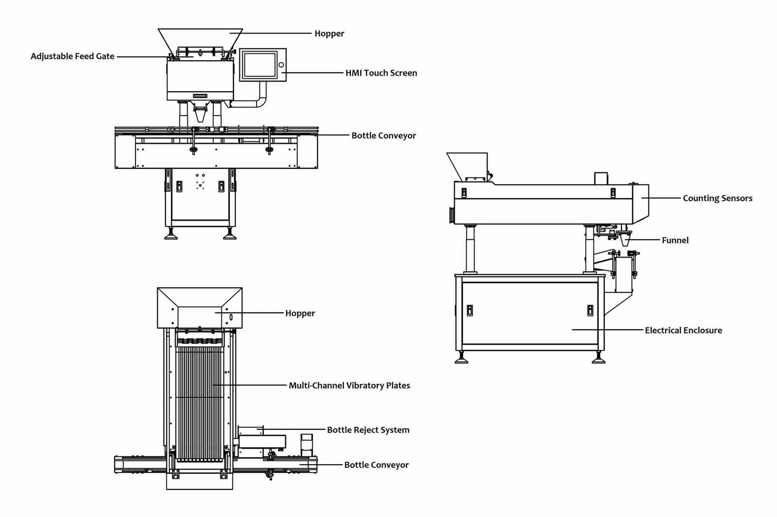
The advancement of visual representation methods is poised to revolutionize various fields, enhancing clarity and facilitating communication. As we move forward, the integration of innovative technologies will redefine how complex concepts are illustrated and understood. Enhanced interactivity, automation, and accessibility will play pivotal roles in shaping these future visuals.
One significant trend is the rise of augmented and virtual reality. These immersive technologies enable users to engage with visualizations in three-dimensional space, allowing for a more intuitive grasp of intricate relationships and structures. By placing users in a simulated environment, these tools can foster deeper comprehension and collaboration.
Another critical development is the incorporation of artificial intelligence. Smart algorithms will analyze vast datasets to generate dynamic representations that adapt in real-time. This capability not only streamlines the creation process but also ensures that visuals remain relevant and informative as new information emerges.
Furthermore, the push towards cloud-based solutions will enhance collaboration among teams scattered across different locations. With shared access to visuals, stakeholders can contribute insights and modifications seamlessly, leading to more refined outcomes.
Lastly, as inclusivity becomes increasingly important, there will be a stronger focus on creating accessible representations for diverse audiences. This will involve employing universal design principles to ensure that all users, regardless of their background or abilities, can effectively engage with and interpret visual content.