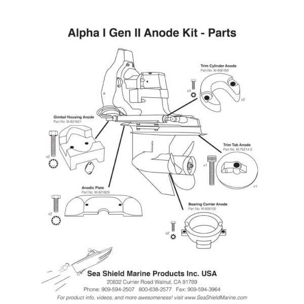
Understanding the structure and interaction of various mechanical elements is crucial for maintaining any system in peak condition. This section focuses on identifying key components, explaining their roles, and how they contribute to the overall functionality of the mechanism.
Each part plays a specific role in ensuring smooth operation. By recognizing these elements, you can better appreciate their importance and the way they work together to form an efficient system. Detailed knowledge of individual components will aid in both troubleshooting and maintenance.
Maintenance and regular inspections are essential for preventing issues, and knowing the core elements helps in identifying potential problem areas quickly. With this guide, you’ll have a clearer understanding of the essential elements involved.
Essential Components of Alpha One Gen 1
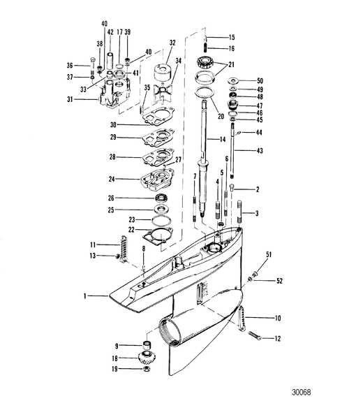
The propulsion system relies on a combination of critical elements that work together to ensure optimal performance. Understanding these elements is key to maintaining the system and ensuring its longevity. Each part has a distinct function, contributing to the overall efficiency and reliability of the equipment.
| Component | Function | ||||||||||||||||||||||||||||||||||||||||
|---|---|---|---|---|---|---|---|---|---|---|---|---|---|---|---|---|---|---|---|---|---|---|---|---|---|---|---|---|---|---|---|---|---|---|---|---|---|---|---|---|---|
| Gear Assembly | Ensures proper rotation and transmission of power to the propeller. | ||||||||||||||||||||||||||||||||||||||||
| Water Pump | Maintains the cooling system by circulating water throughout the engine. | ||||||||||||||||||||||||||||||||||||||||
| Propeller Shaft | Transfers power from the engine to the propeller, driving the vessel forward. | ||||||||||||||||||||||||||||||||||||||||
| Gimbal Bearing | Allows the drive to pivot smoothly while supporting rotational motion. |
| Component | Function | ||||||||||||||||||||||||||||||||||
|---|---|---|---|---|---|---|---|---|---|---|---|---|---|---|---|---|---|---|---|---|---|---|---|---|---|---|---|---|---|---|---|---|---|---|---|
| Transmission Assembly | Transfers power from the engine to the drive system, ensuring smooth propulsion. | ||||||||||||||||||||||||||||||||||
| Coupler | Connects various elements of the drive, allowing for controlled motion. |
| Component | Description |
|---|---|
| Water Pump | Responsible for circulating coolant through the system to absorb heat. |
| Heat Exchanger | Facilitates the transfer of heat from the coolant to the surrounding water, effectively lowering the temperature. |
| Thermostat | Regulates the flow of coolant based on the temperature, ensuring consistent operation. |
| Hoses | Transport coolant between various components, designed to withstand high pressure and temperature. |
| Cooling Jacket | Encases the engine block to absorb excess heat, promoting efficient cooling. |
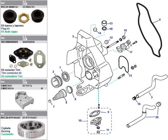
Understanding the layout of the cooling assembly is crucial for maintenance and troubleshooting, ensuring longevity and optimal functionality of the marine system.
Important Seals and Gaskets in Operation
The effective functioning of any mechanical assembly heavily relies on the integrity of various sealing components. These crucial elements play a significant role in preventing fluid leaks and ensuring optimal performance throughout the system. Their proper installation and maintenance are vital to sustaining operational efficiency.
Seals and gaskets are specifically designed to create a tight barrier between surfaces, minimizing the risk of leakage and contamination. High-quality materials are essential in their construction, as they must withstand varying pressures and temperatures. Over time, these components may degrade due to wear, exposure to harsh environments, or inadequate installation, leading to potential failures.
Regular inspection and timely replacement of these elements are necessary to maintain the overall reliability of the machinery. Implementing a proactive maintenance schedule can significantly reduce the likelihood of unexpected breakdowns, enhancing the longevity and functionality of the entire system.
Transom Assembly and Mounting Points
This section provides an overview of the structure and attachment locations associated with the transom, a critical component that ensures stability and support for the assembly. Understanding these elements is essential for proper installation and maintenance.
Key Components of the Transom Assembly
- Transom plate: This is the primary support structure that connects the assembly to the vessel.
- Mounting brackets: These facilitate the secure attachment of the assembly to the transom.
- Bolts and fasteners: Essential for ensuring that all components are tightly secured, preventing any movement or instability.
Installation Considerations
- Ensure all components are clean and free of debris before installation.
- Verify the alignment of mounting points for a precise fit.
- Use appropriate tools and torque specifications when fastening components.
Proper attention to the transom assembly and its mounting locations will enhance the overall performance and safety of the setup.
Hydraulic Systems and Their Components
Hydraulic systems play a vital role in various machinery, utilizing fluid power to perform numerous functions. These mechanisms are designed to transfer energy through liquids, enabling efficient movement and operation of various devices. Understanding the essential elements of these systems is crucial for their maintenance and functionality.
At the core of hydraulic systems are several critical components that work together seamlessly. Below is a brief overview of these key elements:
| Component | Function |
|---|---|
| Hydraulic Pump | Generates flow and pressure within the system. |
| Hydraulic Cylinder | Converts fluid energy into mechanical motion. |
| Valves | Control the direction and flow of hydraulic fluid. |
| Reservoir | Stores hydraulic fluid for circulation in the system. |
| Filters | Remove contaminants from the hydraulic fluid. |
Each of these components contributes to the overall efficiency and effectiveness of hydraulic systems, making them essential in numerous applications.
Trim and Tilt Mechanisms Explored
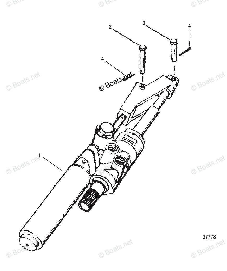
The functionality of marine vessels relies heavily on effective control systems that manage the angle and position of the engine. These mechanisms play a crucial role in optimizing performance, enhancing maneuverability, and ensuring stability while navigating various water conditions. Understanding how these systems operate can significantly improve the overall experience of operating a watercraft.
Understanding the Mechanisms

Trim and tilt systems consist of several components working in harmony to adjust the orientation of the propulsion unit. These systems allow operators to elevate or lower the engine, which influences the boat’s attitude and speed. By modifying the angle, the vessel can achieve better hydrodynamic efficiency, reducing drag and improving fuel economy.
Key Components and Functionality
Central to these systems are hydraulic pumps and cylinders that provide the necessary force for adjustments. The operator can control the tilt and trim through a simple interface, allowing for quick responses to changing water conditions. Effective maintenance of these components is essential to ensure optimal performance and longevity of the mechanisms.
Alpha One Gen 1 Lubrication Parts Diagram
This section provides a comprehensive overview of the components essential for the proper lubrication of the system. Effective maintenance of these elements is crucial for ensuring optimal performance and longevity.
Key Components for Lubrication
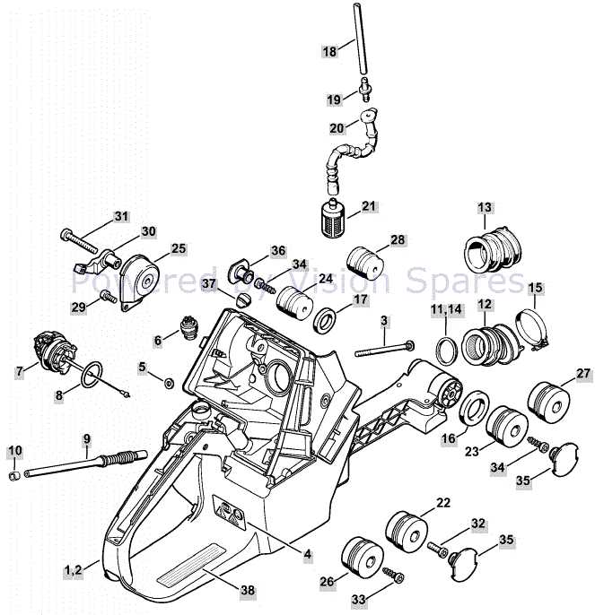
- Oil Reservoir
- Seals and Gaskets
- Oil Pump
- Lubrication Lines
- Filters
Maintenance Recommendations
- Regularly check the oil level in the reservoir.
- Inspect seals and gaskets for wear and tear.
- Ensure the oil pump is functioning correctly.
- Clean or replace filters as needed.
- Follow the manufacturer’s guidelines for oil type and maintenance schedule.
By focusing on these components and following recommended practices, you can enhance the efficiency and reliability of the system.
Commonly Replaced Parts and Their Role
This section provides an overview of frequently swapped components and their significance in the overall functionality of the system. Understanding these elements is crucial for maintaining optimal performance and ensuring longevity.
Many users often find themselves needing to replace specific elements due to wear and tear. Recognizing the importance of these components can enhance the efficiency and reliability of the equipment.
| Component Name | Function |
|---|---|
| Drive Shaft | Transmits power from the engine to the propeller, ensuring efficient propulsion. |
| Seals | Prevent leaks of fluids, protecting internal mechanisms and maintaining pressure. |
| Bearings | Support rotational parts, reducing friction and wear, enhancing performance. |
| Propeller | Creates thrust to move the vessel through water, playing a vital role in navigation. |
