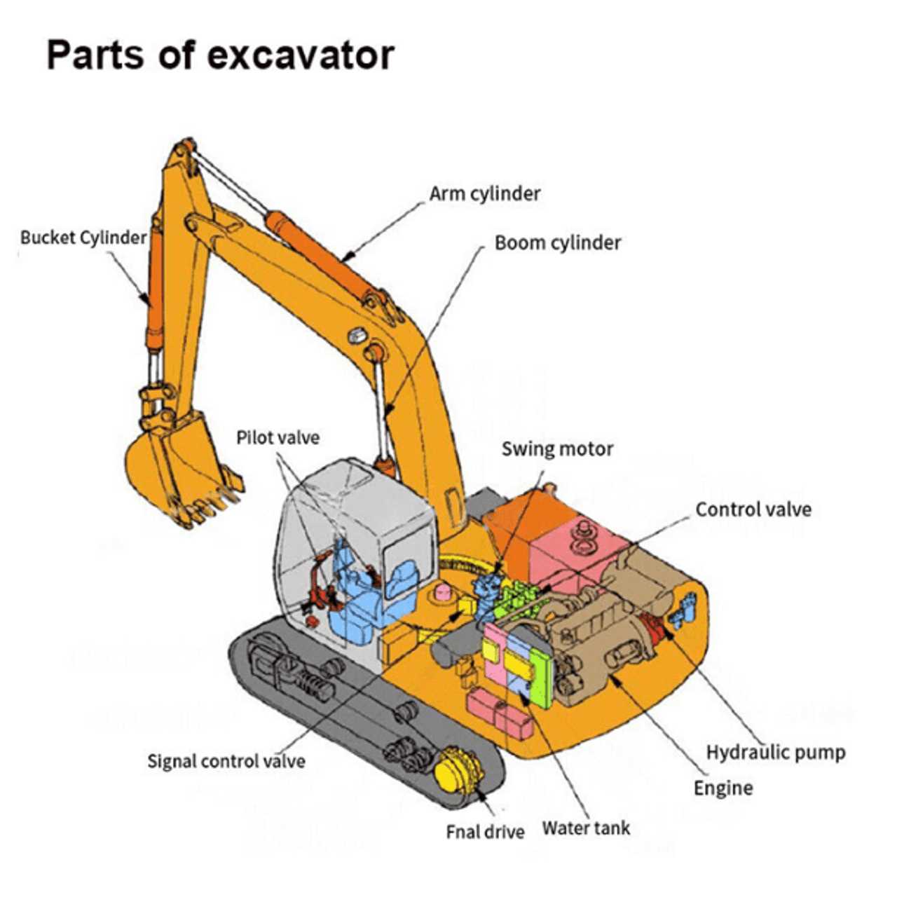
When it comes to maintaining complex machinery, understanding the layout and structure of its essential components is crucial. This section provides a clear and organized view of the most important elements that ensure smooth operation. Whether you’re working on routine maintenance or addressing a specific issue, knowing where each element is located can significantly streamline the process.
Proper identification of these elements not only saves time but also helps prevent costly mistakes. By having a visual reference, you can easily locate specific sections, making repairs or adjustments more efficient. Clear understanding of the system’s structure plays a key role in ensuring the longevity and reliability of the equipment.
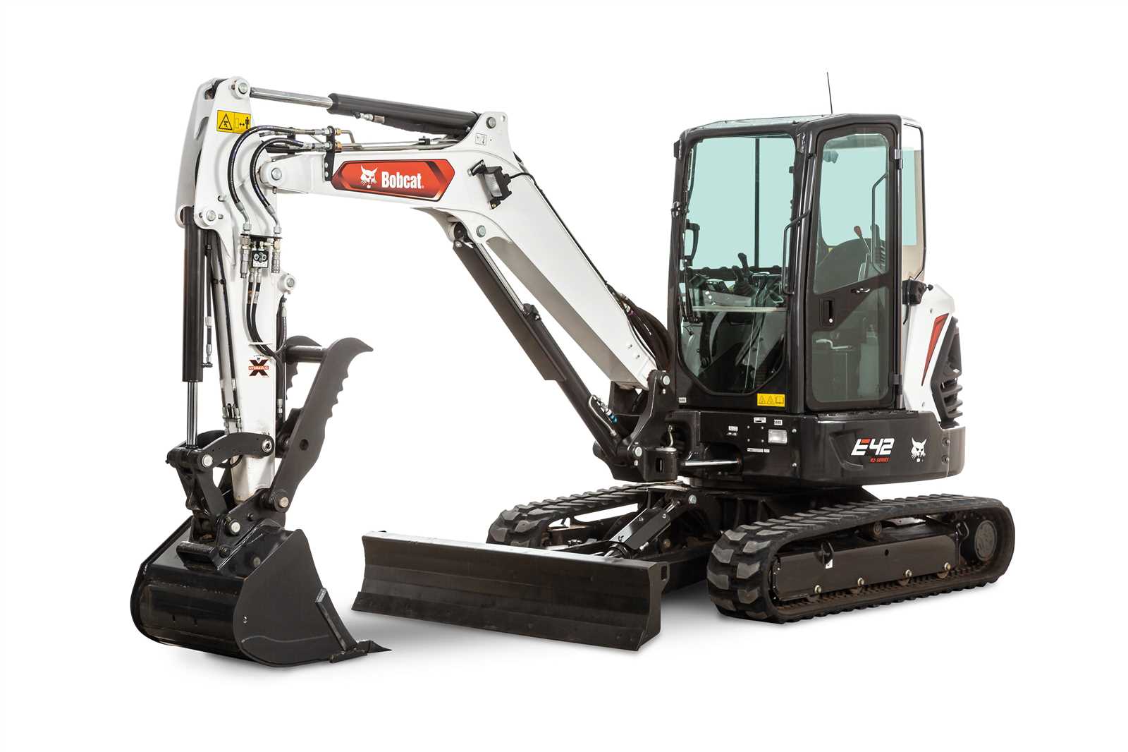
Bobcat E42 Parts Overview
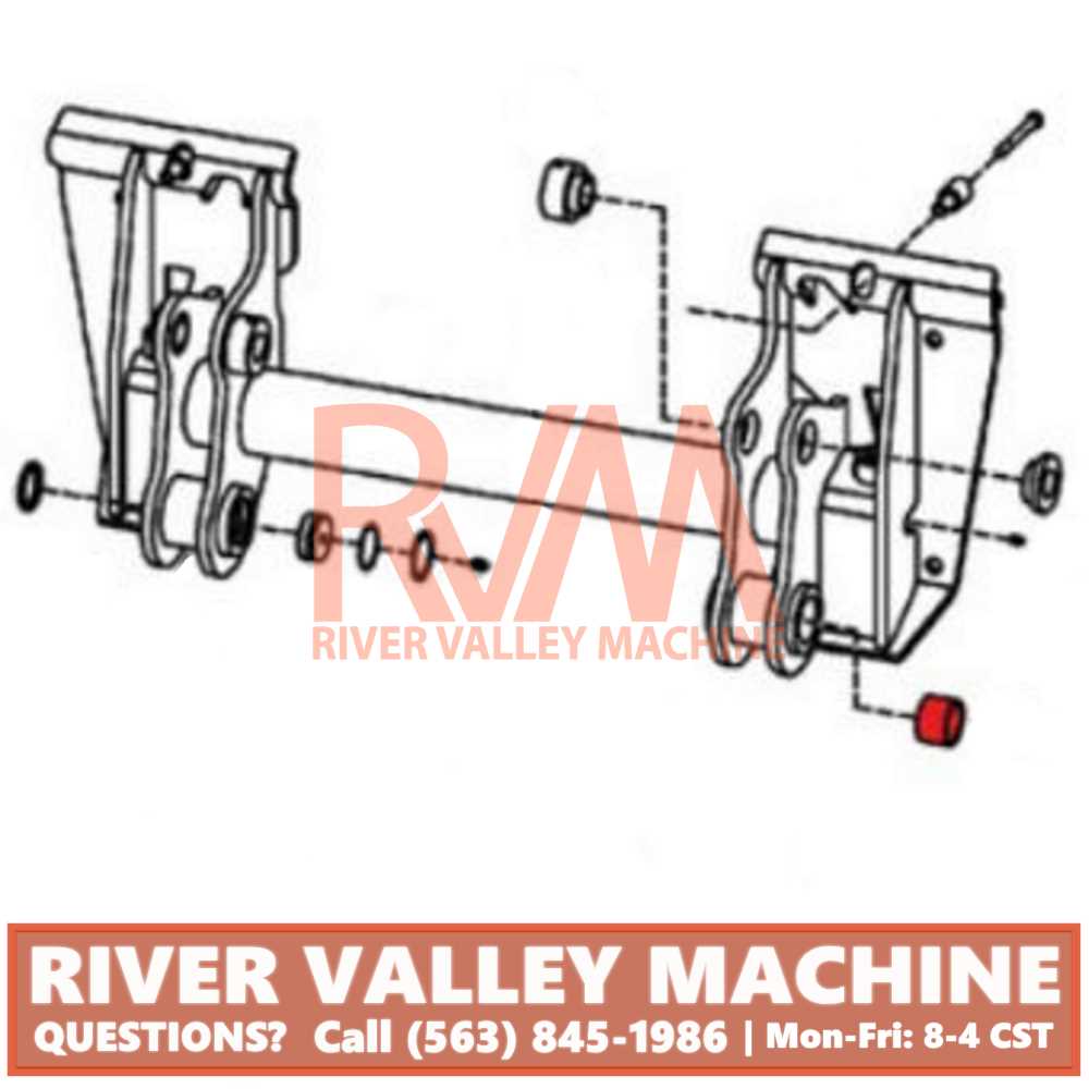
Understanding the structure and components of this compact equipment is essential for optimal performance and maintenance. Each section of the machine is designed with precision to ensure efficient operation, allowing users to handle various tasks seamlessly. By exploring the various assemblies and their roles, it becomes easier to maintain and replace necessary elements when needed.
| Component | Function |
|---|---|
| Engine Assembly | Provides the power needed for efficient operation. |
| Hydraulic System | Controls the movement and digging capabilities. |
| Undercarriage | Supports mobility and stability during use. |
| Operator Cabin | Offers a controlled environment for the operator with easy access to controls. |
| Attachment Interface | Allows for the connection of various tools to perform specialized tasks. |
Engine Components and Assembly
Understanding how the different elements of the engine work together is essential for maintaining and optimizing performance. The assembly involves various crucial elements that contribute to the overall functionality and efficiency of the system.
Main Elements of the Engine
The core of the engine consists of several key parts that must operate in harmony. These include mechanisms responsible for power generation, components that manage fuel intake, and systems that ensure the proper cooling of internal processes. Each of these elements plays a vital role in keeping the system running smoothly.
Assembly Process Overview
The assembly process involves precise fitting of various engine components. Attention to detail during the installation ensures maximum efficiency and reduces the likelihood of issues. Proper alignment, secure connections, and careful calibration of each
Hydraulic System Layout
The hydraulic system is essential for the smooth operation of machinery, providing power for various functions through the controlled flow of fluid. This system relies on a series of interconnected components to ensure efficient movement and operation.
- Pumps are responsible for moving the fluid throughout the system, maintaining pressure and ensuring consistent flow.
- Valves control the direction and rate of flow, allowing precise adjustments to the system’s output and movement.
- Cylinders convert the fluid’s pressure into mechanical force, driving motion in different parts of the equipment.
- Hoses and pipes connect all components, ensuring the fluid travels seamlessly between them without loss or leaks.
By understanding the layout of these components, it’s easier to troubleshoot and maintain the system, ensuring the machinery operates effectively in all conditions.
Track and Undercarriage Details
The track and undercarriage play a crucial role in the machine’s overall stability and mobility, especially when operating in rough or uneven terrain. These components ensure smooth movement and help distribute the machine’s weight efficiently, providing better traction and reducing wear on surfaces.
Main Features
- Durability: The materials used in the track system are designed to withstand harsh environments, offering long-lasting performance and minimal maintenance.
- Enhanced Traction: The track design allows for maximum grip on various surfaces, from soft soil to rocky terrain, ensuring steady and controlled movement.
- Shock Absorption: The undercarriage system is engineered to absorb impacts, reducing stress on the machine’s body and improving operator comfort during extended use.
Components Overview
- Track Links: These interlocking segments form the continuous loop that moves the machine, providing the necessary flexibility and strength.
- Rollers: Positioned beneath the track, rollers help guide and support the weight of the machine as it moves.
- Drive Sprockets: Responsible for propelling the track forward, the sprockets engage with the track links for smooth operation.
- Idlers: These components help maintain the correct tension in the track, ensuring optimal performance and reducing wear.
Cab Interior Parts Breakdown
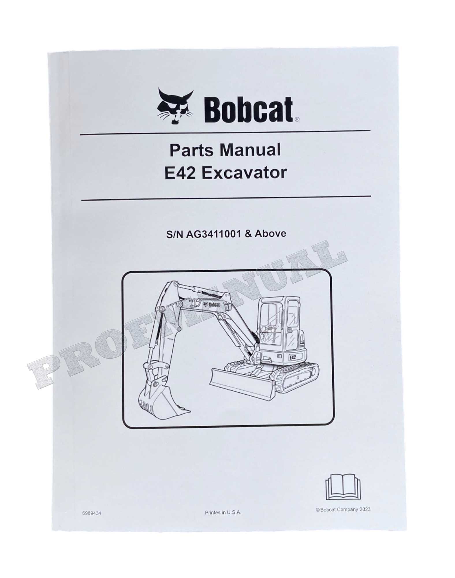
The interior of the cabin is designed with multiple components working together to create a functional and comfortable environment. Each element inside serves a specific role, contributing to both operator efficiency and comfort. Understanding the arrangement of these components is essential for maintenance and potential upgrades.
| Component | Description |
|---|---|
| Seat Assembly | Provides adjustable seating to ensure operator comfort during extended use. |
| Control Levers | Allows the operator to manage various functions of the machine with precision. |
| Pedals | Foot-operated controls used for specific movements or operations. |
| Dashboard | Displays key information such as operational status, fuel levels, and alerts. |
| Storage Compartments | Convenient spaces for storing tools, manuals, and personal items. |
Control System Components
The control system of a compact machine plays a crucial role in ensuring seamless operation and efficient performance. This section outlines the key elements that contribute to the overall functionality and user experience, highlighting their significance in managing various tasks effectively.
- Control Panel: The interface through which operators interact with the machine, allowing for adjustments and settings to be made for optimal performance.
- Sensors: Devices that monitor various parameters such as temperature, pressure, and position, providing real-time feedback to enhance operational safety and efficiency.
- Actuators: Components that convert control signals into mechanical motion, enabling precise movements of various machine parts.
- Wiring Harness: A collection of electrical wires and connectors that facilitate communication between different control system elements, ensuring reliable operation.
- Controllers: The brains of the system, processing inputs from sensors and sending commands to actuators, effectively managing the machine’s functions.
Understanding these components is essential for anyone looking to maintain or troubleshoot the machine. Proper maintenance and knowledge of each part’s function can significantly impact the overall efficiency and longevity of the equipment.
Cooling System Diagram
The cooling system plays a crucial role in maintaining optimal operating temperatures within machinery. Its primary function is to dissipate heat generated during the engine’s operation, ensuring that components function efficiently without overheating. Understanding the layout and components of this system is essential for effective maintenance and troubleshooting.
Key components of the cooling system include:
- Radiator: Responsible for transferring heat away from the engine.
- Water Pump: Circulates coolant through the system.
- Thermostat: Regulates coolant flow based on temperature.
- Coolant Hoses: Transport coolant between components.
- Expansion Tank: Allows for coolant expansion and provides a reserve.
Maintaining the efficiency of the cooling system is vital. Regular checks and servicing can prevent overheating issues and extend the lifespan of the machinery. Proper knowledge of the cooling layout aids in quick identification of potential problems and facilitates effective repairs.
Electrical System Parts List
The electrical system of a machine is essential for its proper functioning and overall efficiency. This section provides an overview of the various components that make up the electrical framework, ensuring that the equipment operates smoothly and effectively. Understanding these elements is crucial for maintenance and troubleshooting purposes.
| Component Name | Description | Part Number |
|---|---|---|
| Battery | Supplies electrical power to the system | 123456 |
| Starter Motor | Engages the engine to initiate operation | 789012 |
| Alternator | Generates electrical current while the engine runs | 345678 |
| Wiring Harness | Connects various electrical components | 901234 |
| Fuses | Protects the electrical circuit from overload | 567890 |
| Relay | Controls the flow of electricity to specific components | 135792 |
Fuel System Layout
The fuel system plays a crucial role in the overall functionality of machinery, ensuring that the engine receives the necessary fuel for optimal performance. A well-designed layout not only enhances efficiency but also simplifies maintenance tasks. Understanding the components and their arrangement is vital for troubleshooting and repairs.
Key Components
- Fuel Tank: Stores the fuel, providing a ready supply for the engine.
- Fuel Pump: Transfers fuel from the tank to the engine, maintaining consistent pressure.
- Fuel Filter: Cleans the fuel before it enters the engine, preventing contaminants from causing damage.
- Fuel Lines: Carry the fuel from the tank to the engine, designed to withstand high pressure.
- Injectors: Atomize the fuel, allowing for efficient combustion in the engine cylinders.
Layout Considerations
- Accessibility: Components should be positioned for easy access during maintenance.
- Flow Direction: Ensure the layout promotes optimal fuel flow, reducing the risk of clogs.
- Heat Management: Components should be placed to minimize exposure to excessive heat, which can degrade fuel quality.
- Safety: Proper separation of components can prevent leaks and enhance overall safety.
Arm and Boom Parts Description
This section provides an overview of the essential components that make up the lifting and reaching mechanism of the machine. Understanding these elements is crucial for effective operation and maintenance.
- Arm: This is the primary segment responsible for extending the reach of the equipment. It is designed to provide strength and stability during various tasks.
- Boom: The boom connects the arm to the main body of the machine. It allows for the upward and downward movement, enabling the operator to handle materials at different heights.
Key elements associated with the arm and boom include:
- Hydraulic Cylinders: These components are vital for the movement of the arm and boom, providing the necessary force to lift and lower loads.
- Pivot Points: Locations where the arm and boom rotate. These points are engineered for durability to withstand repeated stress.
- Linkages: Mechanical connections that transfer motion and force between different components, ensuring smooth operation.
- Mounting Brackets: These secure the arm and boom to the chassis of the machine, ensuring stability and alignment during operation.
Proper understanding and maintenance of these components will enhance the performance and longevity of the machinery.
Attachments and Mounting Options
In the world of compact machinery, understanding the various tools and mounting solutions is crucial for enhancing versatility and performance. These accessories not only expand the functionality of equipment but also enable operators to tackle a broader range of tasks efficiently. Selecting the right attachments can significantly improve productivity, making it essential to consider the available options and their compatibility with specific models.
Common attachments include buckets, forks, and hydraulic tools that cater to diverse applications such as excavation, lifting, and landscaping. Each attachment serves a unique purpose, and ensuring proper mounting is vital for safety and effectiveness. Utilizing appropriate hardware and following manufacturer guidelines during installation can enhance operational efficiency while minimizing wear and tear on the machine.
Furthermore, it is important to assess the weight and size of each attachment to maintain balance and stability during operation. Custom mounting solutions may also be available, allowing for tailored setups that meet specific needs. Understanding these elements is key to maximizing the capabilities of compact equipment and ensuring smooth performance across various tasks.
Maintenance Parts and Service Tips
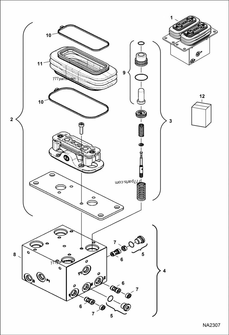
Proper upkeep of machinery is essential for ensuring optimal performance and longevity. Understanding the essential components and following best practices can significantly enhance operational efficiency. This section provides valuable insights into critical components and service recommendations for effective maintenance.
Essential Components for Regular Care
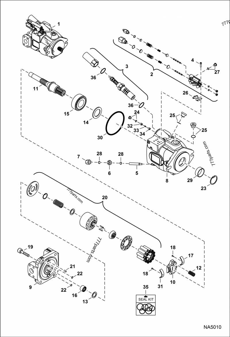
Frequent inspection of vital components is crucial. Key items to monitor include filters, fluids, and belts. Regularly replacing worn or contaminated elements prevents potential issues and maintains smooth operation. Additionally, ensuring that all lubricants are applied appropriately helps reduce friction and wear, prolonging the life of essential machinery parts.
Service Recommendations for Longevity
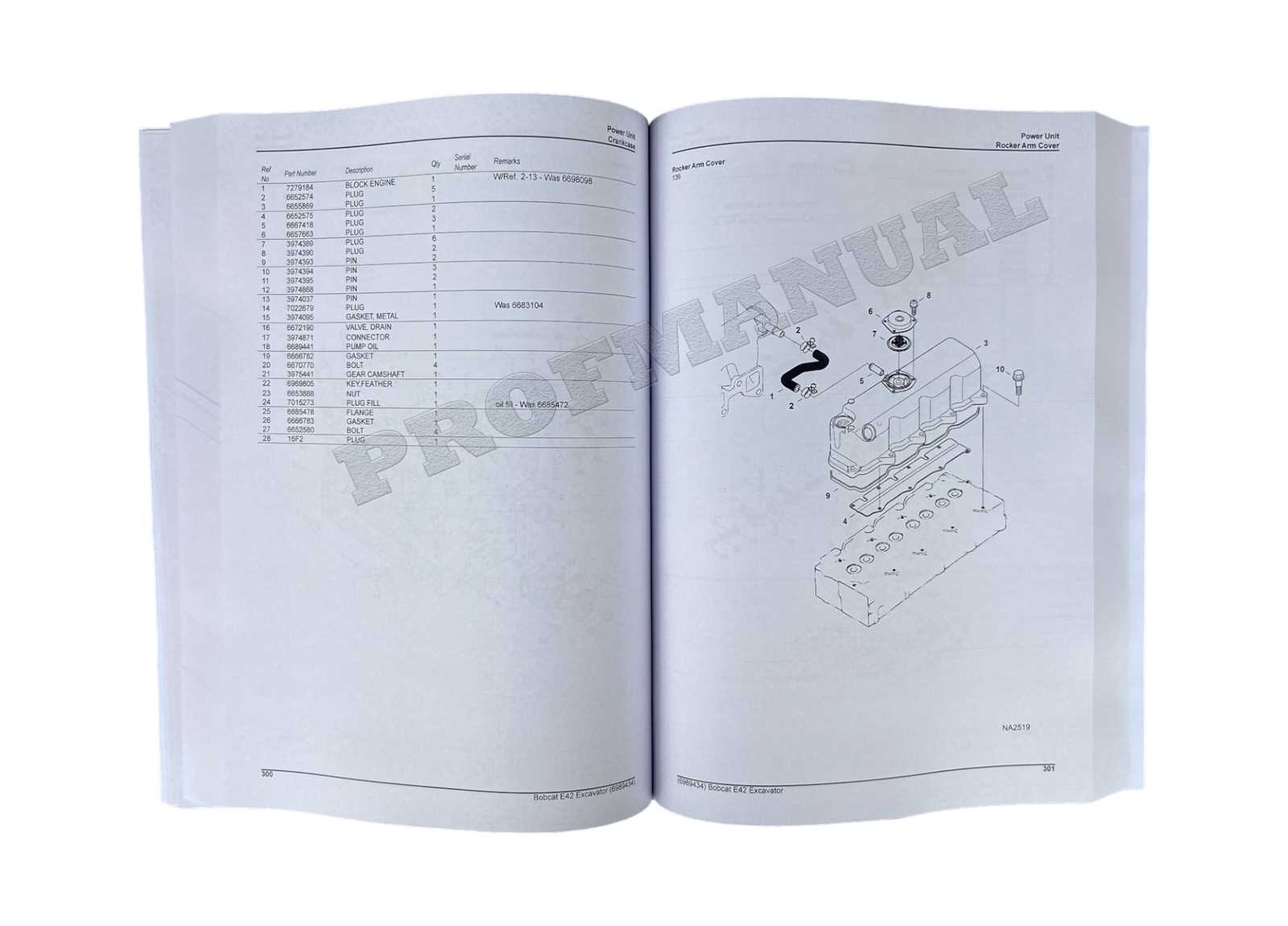
Implementing a consistent maintenance schedule is fundamental. Regular cleaning of the equipment not only enhances appearance but also allows for the early detection of potential problems. Moreover, consulting the manufacturer’s guidelines for recommended service intervals ensures compliance and reliability. Staying proactive with maintenance can help avoid costly repairs and downtime.