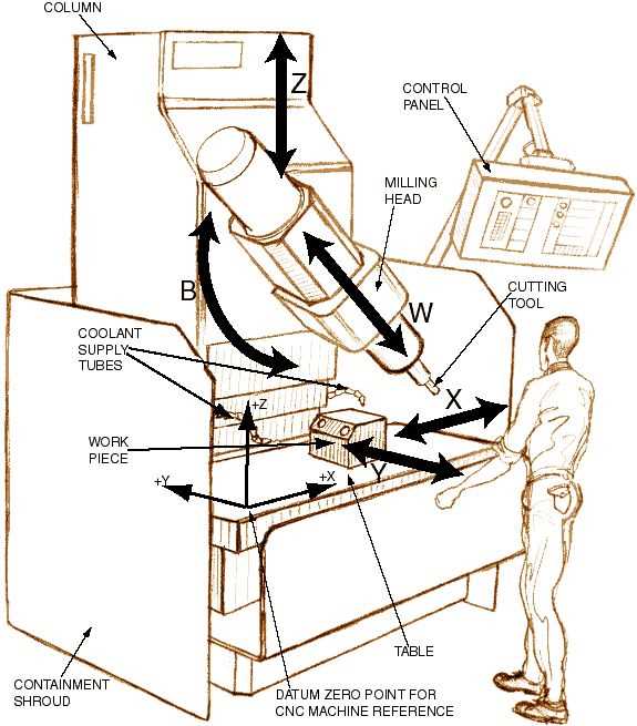
When delving into the world of automated systems, understanding how different elements work together is essential for building reliable and efficient setups. These systems consist of a variety of interconnected elements, each with its own role in the overall function. By breaking down the structure into its key segments, you can gain a clear picture of how the individual sections collaborate to achieve precise movements and control.
Mechanical assemblies, control units, and motion drivers are all integral to the smooth operation of the system. Understanding their positions and connections can make troubleshooting and maintenance more manageable, helping ensure continuous functionality. A closer look at the layout of these components will reveal how each section interacts with the others to form a cohesive structure.
Having a clear overview of the internal structure allows for better optimization of system performance. Recognizing the importance of each segment in the overall operation enables better decision-making when it comes to upgrades or repairs. This understanding contributes to
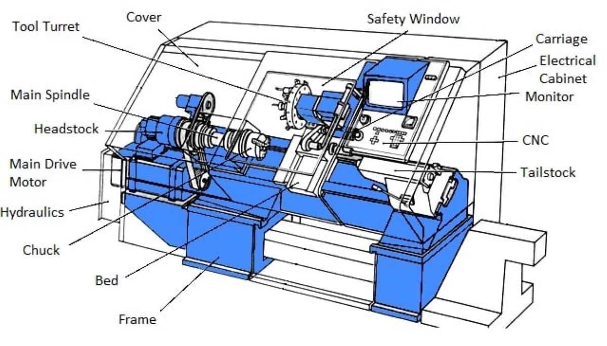
Overview of CNC Machine Components
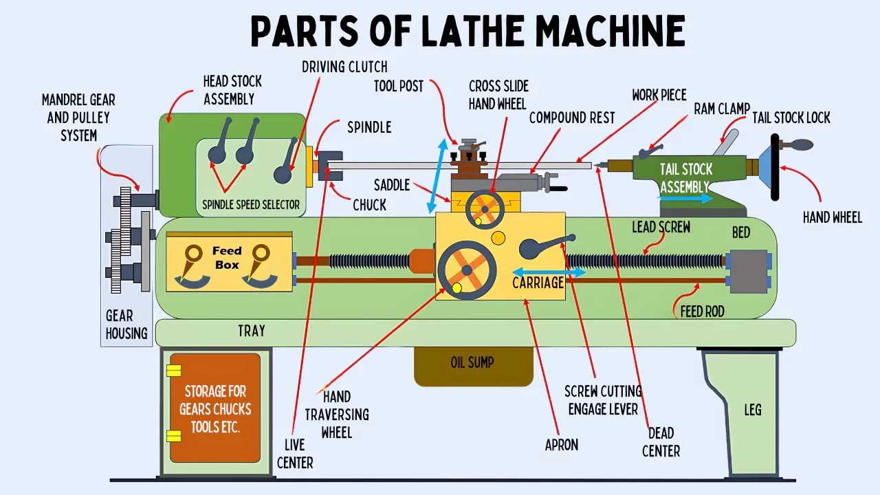
A wide range of machinery is built from multiple interconnected elements, each serving a specific role in the operation. These devices are designed to perform tasks with precision, involving both mechanical and electronic elements working in harmony. Each component contributes to the smooth execution of the process, ensuring accuracy and efficiency during the operation.
Key Structural Elements

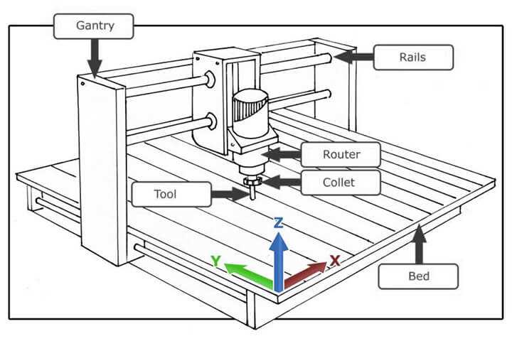
The frame serves as the foundation, providing stability and support. Attached to it, various motion systems allow controlled movement, which is crucial for achieving desired results. These systems include motors and rails, guiding the movement along specific axes with high precision.
Control and Processing Units
The core of the machine’s functionality lies in its control units. These units interpret instructions and guide
Key Structural Elements in CNC Systems
The construction of automated machinery relies on essential components that ensure precision, stability, and efficiency. Each part plays a significant role in creating a well-functioning setup, and understanding the basic structural elements is key to maintaining smooth operation.
Frame and Support Structure
The backbone of the system, the frame provides a solid foundation for all other elements. A sturdy and rigid frame is necessary to minimize vibration and maintain accuracy during operation. Materials used for this element must offer durability and resistance to environmental factors.
- Provides stability and alignment
- Supports other key components
- Helps maintain precision during tasks
- Automated swapping of tools for enhanced efficiency
- Precision movements for consistent results
- Accommodates multiple tool types for different applications
- Reduces manual intervention and operational delays
- They provide consistent motion, ensuring smooth operation during various processes.
- These systems contribute to the precision of movements, allowing for intricate and detailed work.
- Reliable drive mechanisms reduce wear and tear, prolonging the equipment’s lifespan.
- They enhance the efficiency of the system, reducing energy consumption and increasing productivity.
Understanding Motor Function in CNC Devices
In automated machinery, motors play a vital role in ensuring smooth and precise movement. The efficiency and accuracy of the system depend heavily on the correct functioning of the motors, which are responsible for driving the mechanical components. Understanding how these motors work helps in optimizing performance and troubleshooting any issues that may arise.
Types of Motors and Their Characteristics
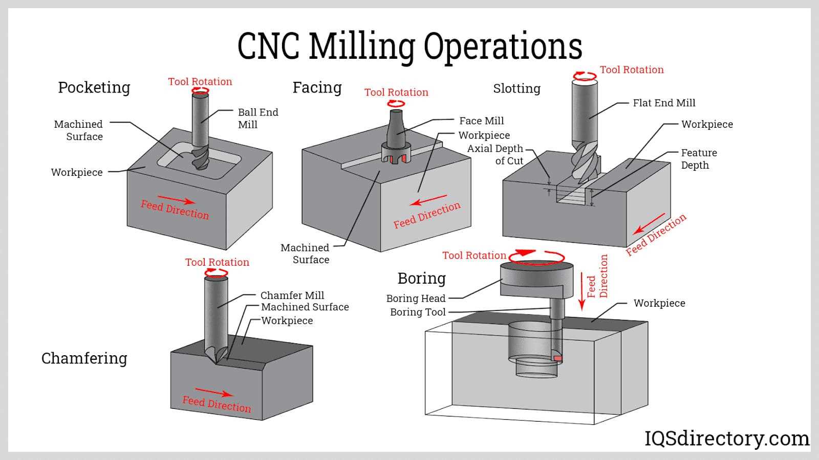
There are various types of motors used in automated systems, each with unique features and benefits. Some are designed for rapid motion, while others prioritize precision and control. Knowing the differences between them allows users to select the right motor for specific tasks and conditions.
| Motor Type | Key Features | ||||||
|---|---|---|---|---|---|---|---|
| Stepper Motor | Offers high precision
Spindle Unit: Core of CNC MachiningThe spindle is essential for precise and efficient material shaping, serving as the driving force behind the movement of cutting tools. It ensures stability and accuracy by rotating the tool at high speeds, allowing it to perform various operations. Its role is pivotal in determining the overall performance and quality of the machining process. In many cases, the spindle’s structure integrates cooling and lubrication systems to maintain optimal functioning during extended use. Additionally, its ability to accommodate different tool types adds versatility, making it suitable for a wide range of materials and tasks. Proper maintenance and calibration of the spindle are crucial to prevent wear and ensure consistent output. A well-maintained unit contributes significantly to the efficiency and precision of the entire machine, making it a critical component in any machining operation. Guideways and Rails: Precision in Motion
The smooth and accurate movement of mechanical components is essential for any automated system. The structures responsible for this motion must ensure stability, minimal resistance, and high repeatability. Achieving seamless linear motion requires robust designs that allow key elements to glide efficiently while maintaining their alignment under various operational stresses. Guideways play a crucial role in ensuring that moving elements stay on their designated path. These components are designed to offer maximum precision by minimizing friction and wear over time. By maintaining a rigid support, they enable accurate positioning, even during prolonged use or under substantial loads. Equally important are the rails, which provide the surface for smooth travel. Their durability and design are critical for achieving reliable performance. The combination of these components creates a stable environment for various tasks that demand high accuracy and consistency. Power Supply and Control Systems
Reliable power distribution and accurate control mechanisms are essential for the smooth operation of any automated equipment. These elements ensure that various components receive the correct amount of energy while maintaining seamless communication with other parts. This balance is crucial for maintaining performance and avoiding disruptions during tasks. Power ManagementEffective power management focuses on delivering the right voltage and current to different sections of the system. This involves converting energy from the primary source and distributing it to key modules. Each section typically requires specific power levels, so proper regulation is critical.
|
