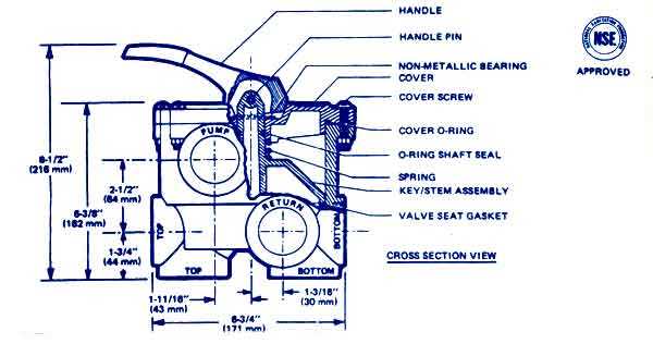
Understanding the inner workings of various equipment requires detailed knowledge of their essential elements. In this section, we explore the critical mechanical and functional units that ensure smooth operation. By gaining insight into these elements, users can improve the efficiency and longevity of their devices.
Identifying key units allows for better maintenance and quicker troubleshooting, ensuring everything operates seamlessly. Each mechanical part plays a significant role in the overall system, contributing to its performance and durability. We aim to provide a thorough guide to help users navigate the different sections effectively.
Maintenance and repairs can be daunting without proper knowledge of each essential element. This section will break down the major components, making it easier for you to understand and manage any future adjustments or replacements.
Overview of Hayward H100ID Components
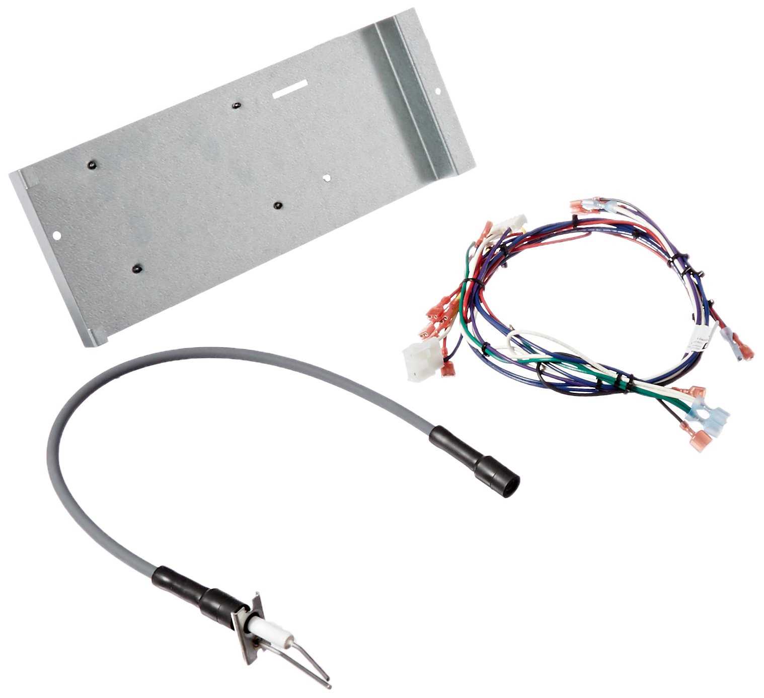
The device in question consists of several key elements that ensure its efficient operation. Each of these parts plays a specific role in maintaining the system’s functionality, working together to provide optimal performance. Understanding these components will help users in troubleshooting, maintenance, and overall equipment management.
- Burner Assembly – responsible for producing the heat required for the system’s operation.
- Heat Exchanger – transfers the generated heat to the surrounding environment, ensuring energy efficiency.
- Control Panel – provides easy access to settings and allows users to monitor the unit’s performance.
- Thermal Sensor – detects temperature levels and helps regulate the system to maintain a stable output.
- Ventilation System – ensures proper airflow and helps to avoid overheating during extended use.
By familiarizing yourself with these essential components, you can better understand how the entire system works together and what role each part plays in its overall performance.
Internal Mechanism Breakdown and Key Parts
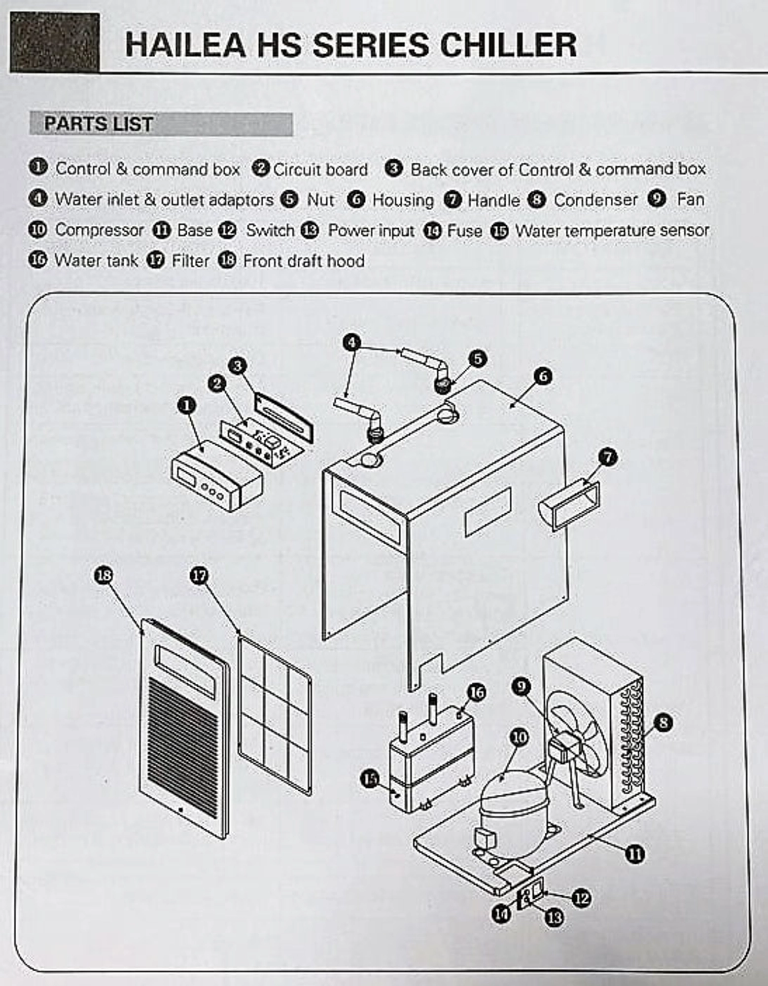
The inner workings of this equipment are designed to ensure efficient performance by integrating several essential components. Understanding how these elements interact is crucial for maintenance and repair. Below, we will explore the critical units that form the core of its operation, ensuring smooth and effective functionality.
Main Components Overview
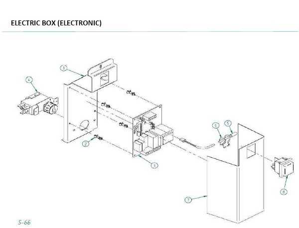
The mechanism relies on several primary units that collaborate to maintain proper function. These elements are strategically placed to maximize efficiency and longevity.
- Combustion Unit – This section is responsible for generating the necessary energy to drive the system.
- Heat Exchanger – A vital element that ensures the transfer of heat to the appropriate channels.
- Ignition System – Provides the initial spark, enabling the system to begin its cycle.
- Control Panel – Allows for the adjustment and monitoring of the system’s various functions.
Auxiliary Elements
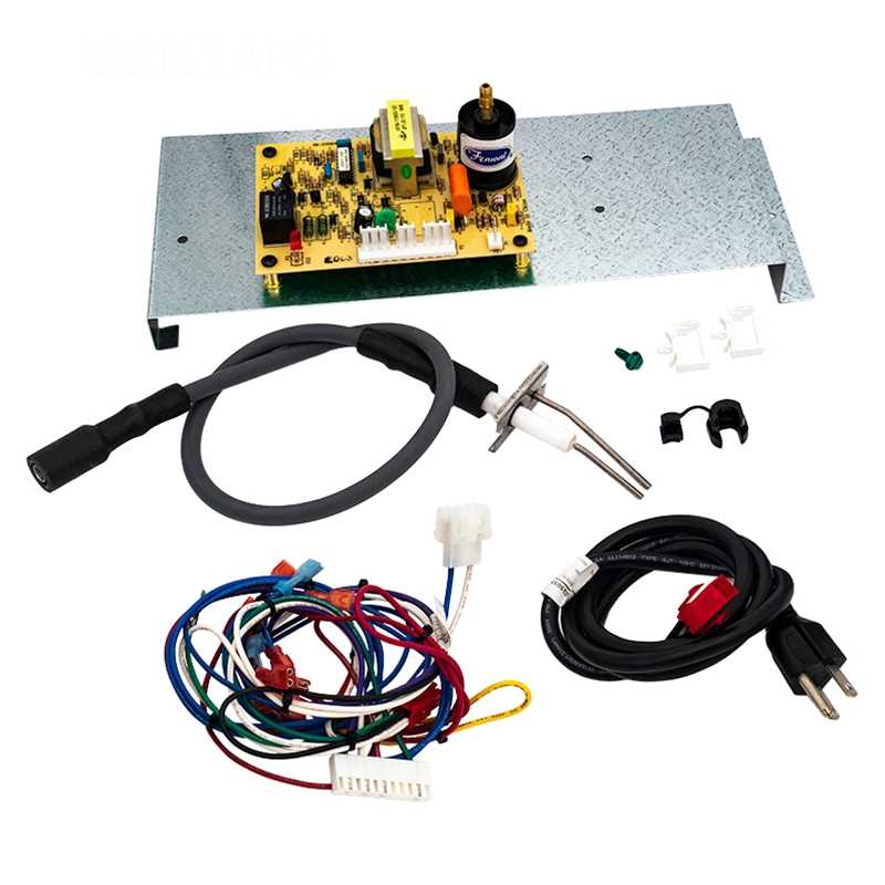
In addition to the primary components, several auxiliary units contribute to the overall performance and safety of the system.
- Thermal Sensors – Monitor temperature levels to prevent overheating.
- Valves – Regulate the flow of air and fuel for optimized combustion.
- Exhaust System – Ensures the safe release of byproducts generated during operation.
Exploring the Burner Assembly Structure
The burner assembly plays a crucial role in the functioning of heating equipment, responsible for converting fuel into heat. Understanding its configuration is important for maintaining efficiency and ensuring smooth operation. In this section, we will delve into the components that make up this assembly, providing insights into their functionality and interconnections.
| Component | Description |
|---|---|
| Ignition System | Initiates the combustion process by igniting the fuel and air mixture. |
| Main Burner | Generates the flame that heats the surrounding environment. |
| Gas Valve | Controls the flow of fuel into the burner for consistent performance. |
| Heat Exchanger | Transfers the generated heat to the intended medium, such as water or air. |
| Safety Controls | Monitors and regulates the system to prevent hazards during operation. |
Fuel System and Ignition Components
The fuel system and ignition components play a crucial role in ensuring smooth operation and efficiency. These systems are responsible for delivering the necessary energy for the appliance to function, as well as igniting the combustion process. Each element within these systems is designed to contribute to a reliable and consistent performance, ensuring that the equipment operates at its optimal level.
Fuel Delivery involves a network of connections that guide the flow of fuel to the necessary chambers. Proper maintenance and attention to these pathways are essential for ensuring that the energy source is provided without interruptions or issues.
Ignition Mechanism is responsible for initiating the combustion process. It involves various components working together to create the necessary spark or heat to ignite the fuel. A well-functioning ignition system guarantees the appliance can start smoothly and operate efficiently over time.
Heat Exchanger Construction and Design
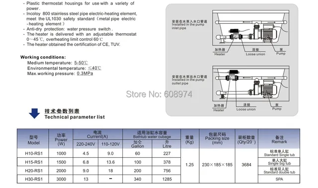
The construction and design of a heat exchanger play a crucial role in its ability to efficiently transfer thermal energy between two mediums. This process is achieved by allowing heat to pass through a series of channels or tubes, ensuring that the two substances involved do not come into direct contact. By utilizing materials with excellent thermal conductivity, the heat exchanger maximizes energy transfer while minimizing loss.
Key Structural Elements of the heat exchanger include a set of tubes or plates, designed to withstand temperature fluctuations and prevent corrosion over time. These components are often arranged in specific patterns to optimize surface area, ensuring that heat is effectively transferred from one medium to another.
Efficiency and durability are important considerations in the overall design. Advanced engineering techniques help improve the flow of fluids, reduce pressure loss, and extend the lifespan of the system. This ensures reliable performance in a wide range of applications, from residential to industrial settings.
Water Flow System Configuration
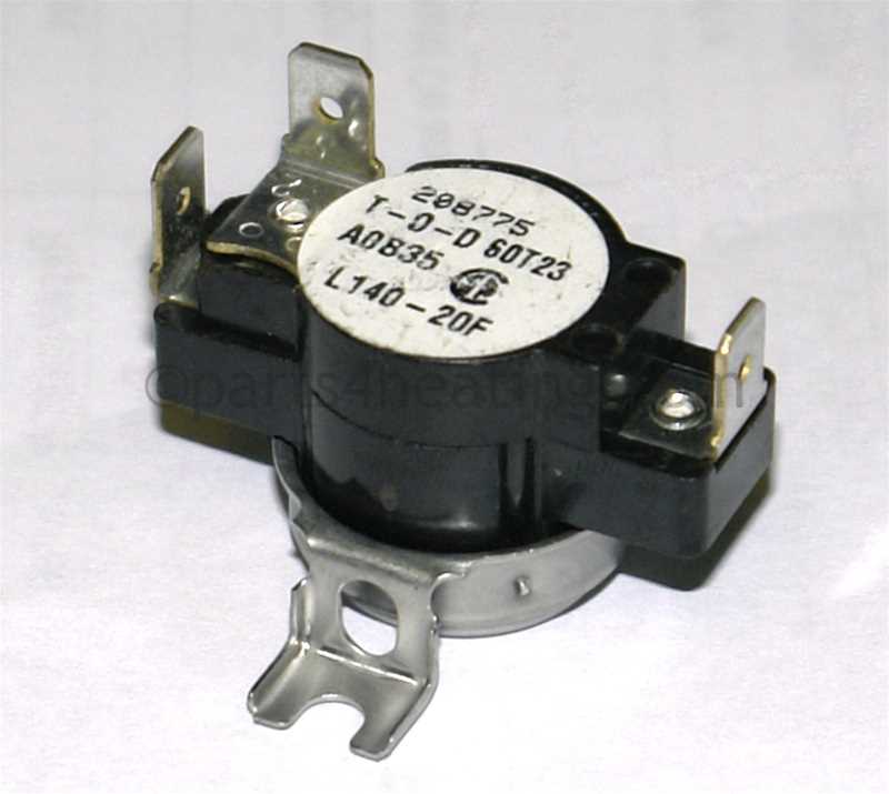
The effective operation of a heating unit relies heavily on the proper arrangement of the water circulation system. A well-structured flow system ensures optimal performance and longevity of the equipment. Understanding the configuration of this system is crucial for maintaining efficiency and achieving desired temperature settings in aquatic environments.
Key Components of the System
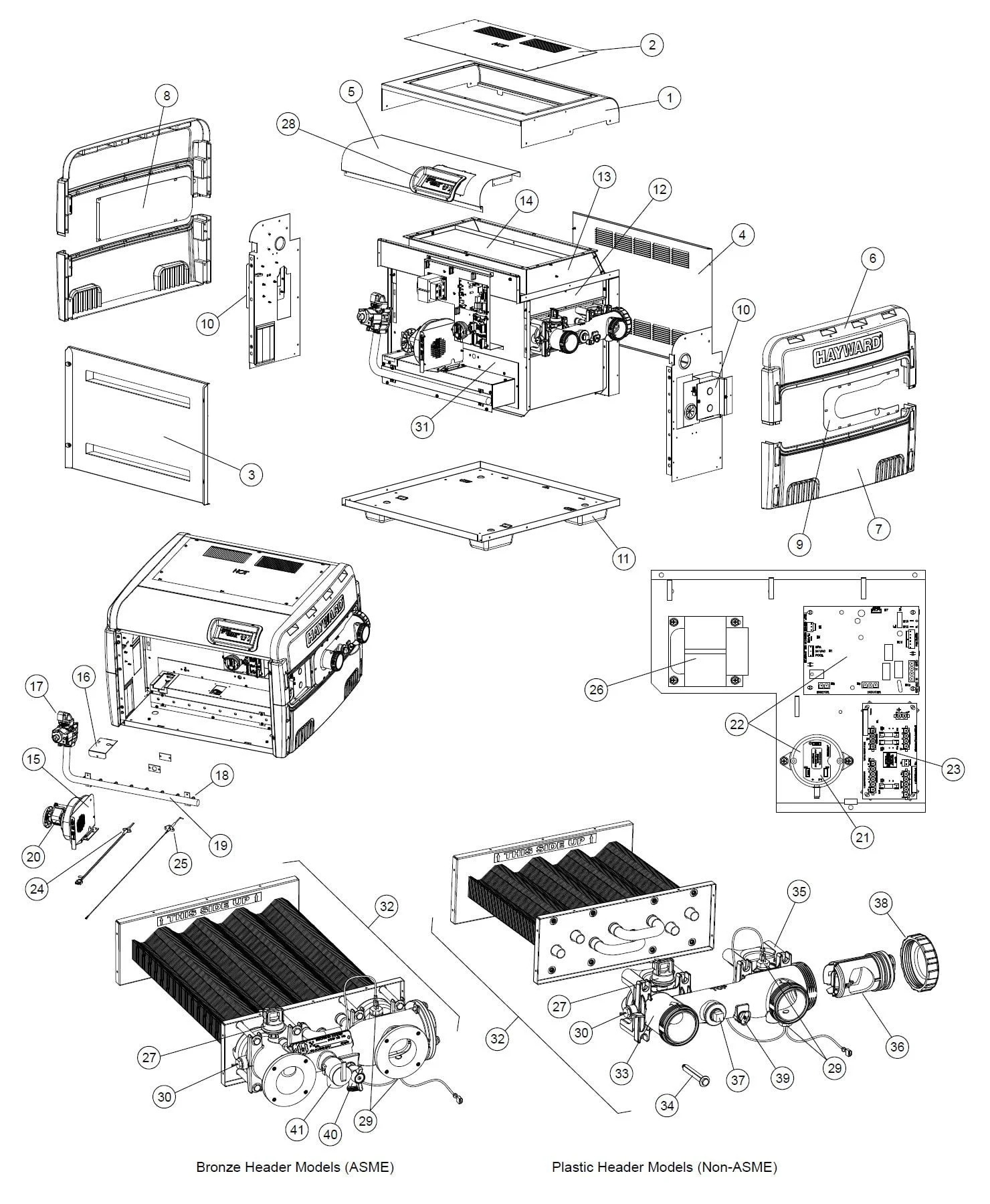
Essential elements of the water flow configuration include pumps, filters, and valves. Each component plays a vital role in regulating the movement of water throughout the heating mechanism. Pumps facilitate circulation, filters purify the water, and valves control the flow direction and pressure, contributing to a harmonious operation.
Importance of Proper Alignment
Correct alignment and installation of these components are critical for avoiding issues such as leaks or inefficient heating. Regular maintenance checks should be performed to ensure that all parts are functioning as intended. This proactive approach not only enhances performance but also prolongs the life of the entire system.
Valve and Control System Overview
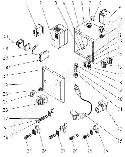
The valve and control mechanism plays a crucial role in managing the flow of fluids within various systems, ensuring optimal performance and efficiency. This section delves into the essential components that contribute to the effective regulation and distribution of water, highlighting their significance in maintaining desired operational conditions.
At the core of this system are the valves, designed to open and close as needed to facilitate or restrict fluid movement. These components can be manually operated or automated, depending on the complexity of the system. Control units often accompany valves, enabling precise adjustments and monitoring of fluid dynamics, thereby enhancing overall system functionality.
In addition, the integration of sensors and feedback mechanisms allows for real-time data collection, contributing to improved responsiveness and reliability. Understanding the various elements involved in the valve and control system is vital for effective maintenance and troubleshooting, ultimately leading to prolonged system longevity and reduced operational costs.
Electrical Connections and Wiring Layout
Understanding the electrical setup and wiring configuration is crucial for ensuring the proper functionality and safety of the equipment. This section outlines the essential aspects of electrical connections, highlighting the importance of correct wiring to prevent malfunctions and hazards.
When establishing electrical links, it is vital to identify each component’s role within the system. This includes recognizing the input and output terminals, as well as understanding the significance of grounding. Proper grounding is necessary to protect both the device and its users from electrical shocks.
Wiring configurations can vary depending on the type of unit and its intended use. It is important to refer to the manufacturer’s guidelines to ensure all connections are made according to specifications. Using the correct gauge wire is essential for maintaining optimal performance and avoiding overheating.
Safety precautions should always be observed when working with electrical systems. Ensure that the power supply is turned off before making any connections. Additionally, double-check all wiring before restoring power to prevent short circuits or potential damage to the equipment.
In summary, a thorough understanding of the electrical connections and wiring layout is fundamental for effective operation and safety. Following proper procedures and guidelines will contribute to the longevity and reliability of the system.
Air Intake and Exhaust Systems
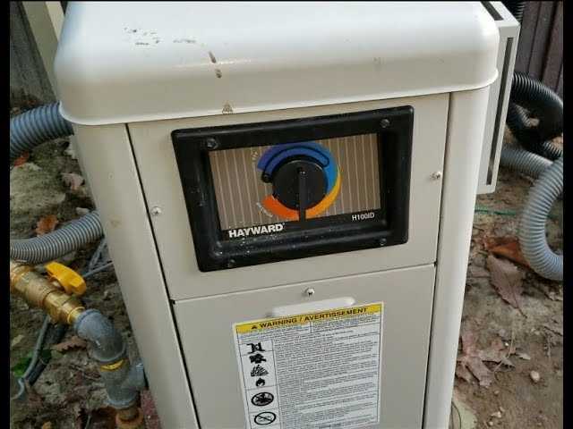
The efficiency of any heating or cooling unit largely depends on the effectiveness of its air intake and exhaust mechanisms. These systems play a crucial role in ensuring optimal airflow, which directly impacts performance and energy consumption. Properly designed and maintained air channels facilitate the movement of air, allowing the equipment to operate at its best while minimizing the risk of overheating or mechanical failure.
Importance of Proper Ventilation
Effective ventilation is essential for maintaining a balanced environment within the equipment. Inadequate airflow can lead to overheating, reduced efficiency, and ultimately, costly repairs. Therefore, ensuring that air can flow freely into and out of the unit is vital for longevity and performance. Regular checks on these systems can prevent potential issues and ensure that the unit operates smoothly.
Maintenance Tips
Routine maintenance of the intake and exhaust systems is important for preserving optimal functionality. Cleaning filters, inspecting ducts for blockages, and ensuring that exhaust outlets are unobstructed are all key practices. Additionally, monitoring for any unusual sounds or changes in airflow can help identify problems before they escalate. Adopting these measures not only enhances performance but also contributes to the overall efficiency of the unit.
Maintenance Tips for Critical Parts
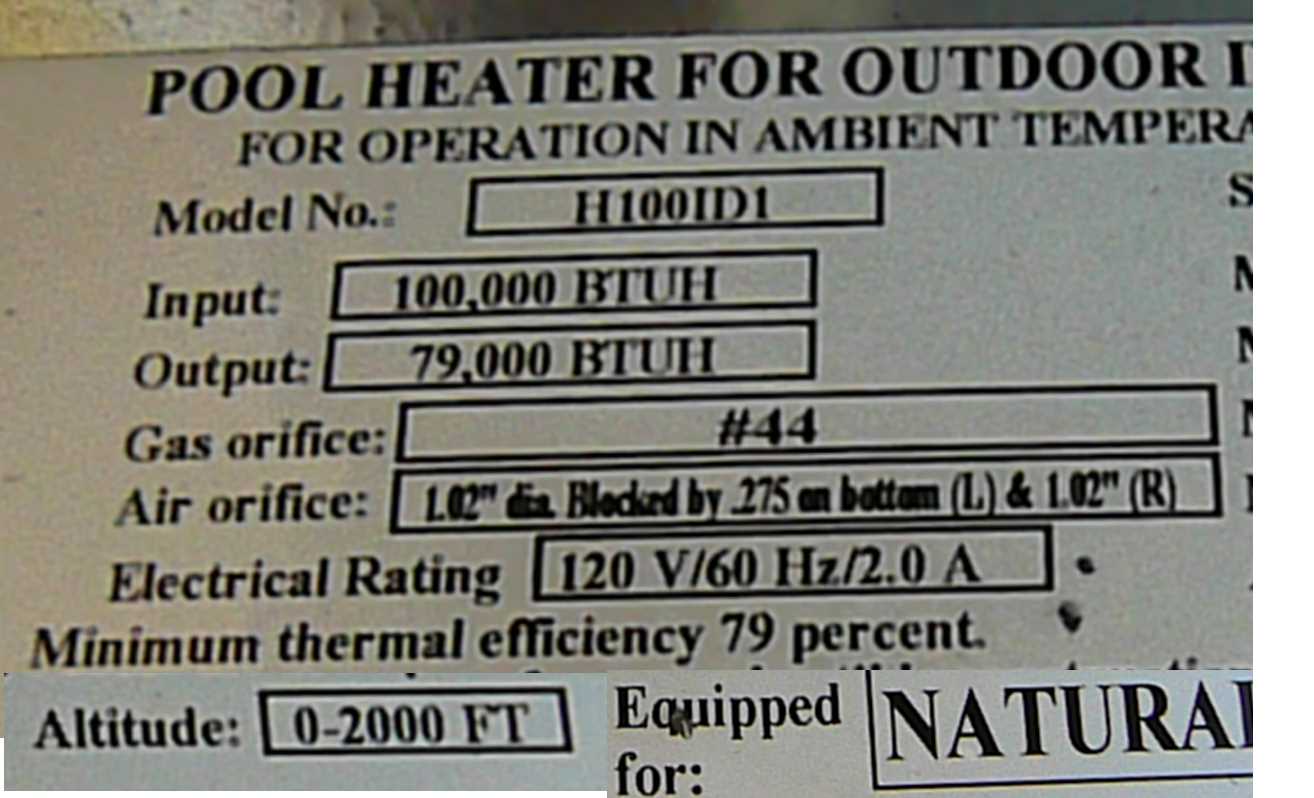
Regular upkeep of essential components is vital for ensuring optimal performance and longevity. By following a few straightforward guidelines, users can effectively minimize wear and tear, leading to enhanced efficiency and fewer disruptions.
- Routine Inspections: Conduct frequent assessments of key elements to identify any signs of damage or wear. Early detection allows for timely repairs or replacements.
- Cleaning: Keep all parts clean and free from debris. Use appropriate cleaning agents to remove buildup, which can hinder performance.
- Lubrication: Apply suitable lubricants to moving components to reduce friction and prevent premature failure. Refer to manufacturer recommendations for the correct type and frequency.
- Calibration: Regularly calibrate mechanisms to ensure they function as intended. Misalignment can lead to inefficiencies and potential breakdowns.
- Seasonal Maintenance: Prepare equipment for seasonal changes by inspecting and servicing components that may be affected by temperature fluctuations.
By adhering to these maintenance practices, users can significantly extend the lifespan of critical elements and enhance overall operational efficiency.
Common Replacement Parts and Options
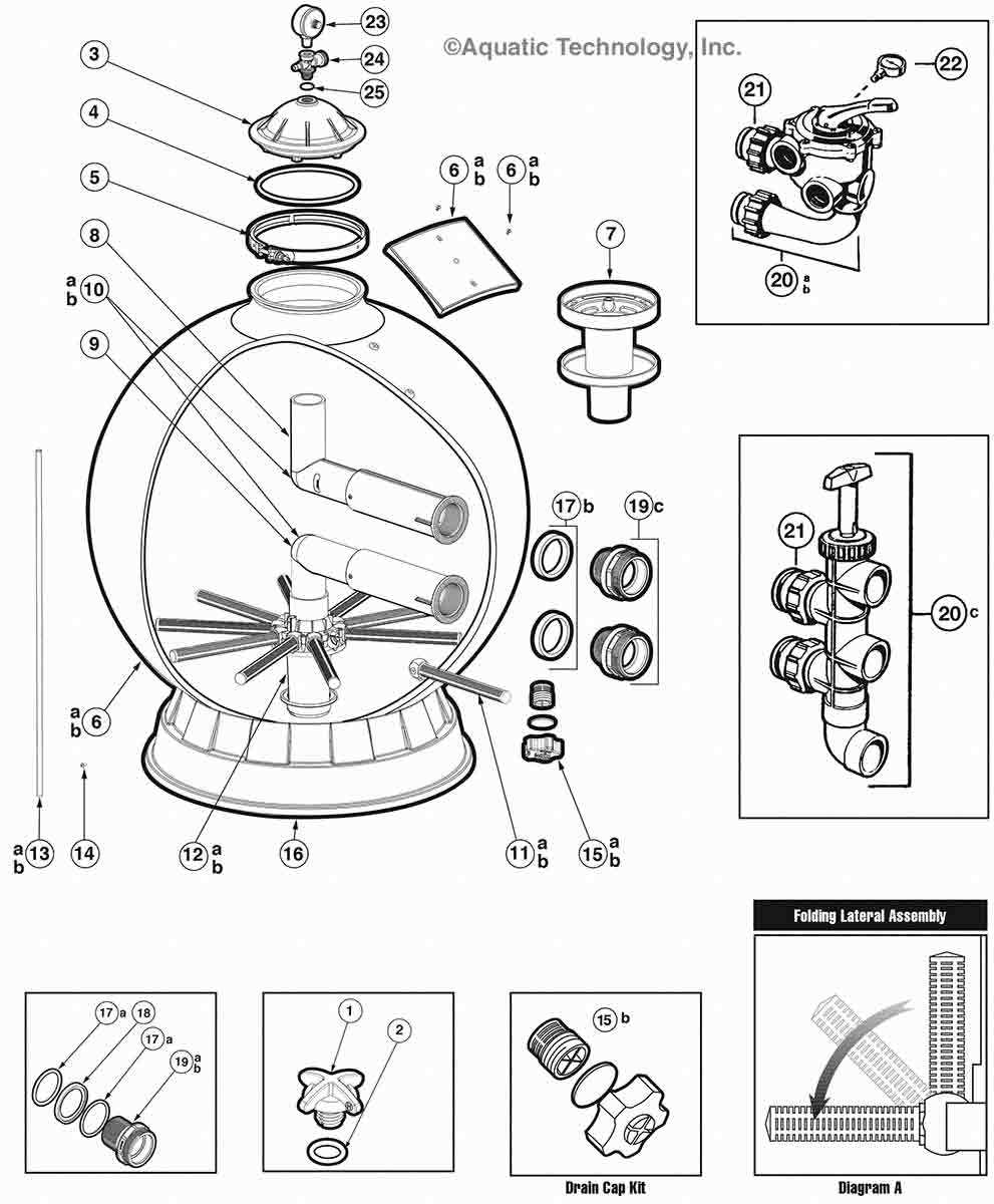
When it comes to maintaining heating equipment, understanding the key components that may require replacement is crucial for optimal performance. This section provides an overview of frequently needed elements and their alternatives, ensuring that users can effectively manage their heating systems.
Below is a table outlining common components that may need to be replaced, along with their descriptions and potential options:
| Component | Description | Replacement Options |
|---|---|---|
| Thermostat | Controls the temperature settings and ensures the unit operates efficiently. | Digital or manual models available. |
| Heating Element | The primary part responsible for generating heat within the system. | Various wattage ratings to suit different needs. |
| Filter | Helps to trap debris and impurities, promoting clean operation. | Reusable or disposable types are common. |
| Pressure Switch | Monitors the pressure levels to prevent operational issues. | Compatible models to match specific systems. |
| Gas Valve | Regulates the flow of gas to the heating system. | OEM and aftermarket options available. |
Identifying and acquiring the right components is essential for ensuring the longevity and efficiency of your heating appliance. Regular checks and timely replacements can lead to improved performance and cost savings in the long run.
Diagram Reading and Troubleshooting Guidance
This section offers insights into interpreting technical illustrations and provides essential support for resolving common issues. Understanding these visuals is crucial for effective maintenance and repair, enabling users to identify components and their functions quickly.
When examining technical illustrations, pay close attention to the labels and symbols used. Each element is typically accompanied by a reference number or letter that correlates with a detailed list. Familiarity with these notations will enhance your ability to navigate the complexities of the system.
For troubleshooting, begin by identifying any discrepancies or malfunctions highlighted in the visual guide. Systematic analysis is key; start with the most straightforward potential causes before delving into more complex issues. Ensure that connections are secure and components are clean and free from obstructions.
In case of persistent problems, refer to the comprehensive resource materials that accompany the technical illustrations. These documents often contain step-by-step instructions and tips tailored to common complications, making them invaluable for effective problem-solving.
By mastering the art of reading these visual aids and utilizing the accompanying guidance, users can significantly enhance their understanding and performance in troubleshooting, ensuring smooth operation of their equipment.