Shows the direction of movement
Common Wear Items for Hesston 6450
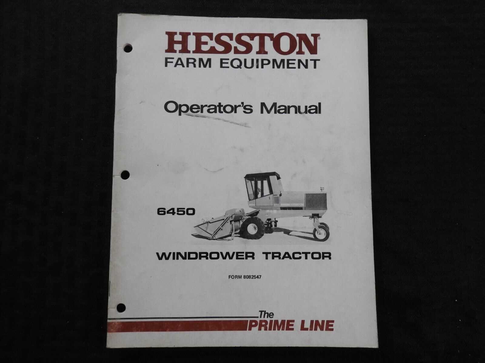
Over time, machines are subjected to various stresses that cause certain components to degrade more quickly than others. Regular maintenance and timely replacement of high-wear components are essential to ensure the longevity and optimal performance of the equipment. Understanding which elements are most likely to wear out can help reduce downtime and prevent costly repairs.
Key areas to monitor include drive belts, which experience constant tension and friction, leading to eventual stretching or fraying. Bearings, exposed to repetitive movements and load, may show signs of wear, such as excessive noise or overheating. The cutting mechanisms also face significant strain, especially in environments with heavy debris or tough materials, causing the blades and knives to dull or bend over time.
Hydraulic systems often suffer from hose degradation or fitting leaks, due to pressure fluctuations and exposure to the elements. Electrical components, like connectors and switches, can corrode or lose contact after extended use, especially in harsh operating conditions. Lastly, tires and suspension elements are prone to damage from uneven terrain, requiring regular inspection for cracks, punctures, or loss of tread.
By proactively identifying and replacing these common wear items, operators can ensure smoother operations and reduce the risk of unexpected breakdowns.
Replacing Bearings in the Cutting Mechanism
Regular maintenance of the cutting assembly ensures smooth operation and prevents costly downtime. Replacing worn-out bearings is a crucial part of this upkeep, as it helps maintain the efficiency of the moving components, allowing for seamless performance during operation. Bearings wear down over time due to friction, and replacing them promptly can extend the lifespan of the machinery.
Identifying Bearing Wear
Before replacing the bearings, it is essential to inspect the components for signs of wear. These may include unusual noises, excessive vibration, or visible damage around the bearing housing. When any of these indicators are present, it suggests the bearings are no longer functioning correctly, and a replacement is necessary. Ensure all moving parts are clean and free from debris before starting the replacement process.
Steps for Bearing Replacement
Step 1: Start by safely disconnecting the machine from its power source to
Troubleshooting Hydraulic System Failures
Hydraulic systems are vital for the efficient operation of various machinery, and any malfunction can lead to significant downtime and costly repairs. Identifying the root causes of issues within these systems is essential for restoring functionality. A methodical approach to diagnosing problems can help pinpoint the specific component or process that is not performing as expected.
Common Symptoms of Hydraulic Issues
Recognizing the typical indicators of hydraulic system failures is the first step in troubleshooting. These symptoms may include unusual noises, erratic movements, or inconsistent pressure levels. Additionally, fluid leaks or overheating can signal underlying problems. Understanding these warning signs allows operators to act swiftly, minimizing potential damage.
Step-by-Step Diagnostic Approach
To effectively address hydraulic failures, follow a systematic diagnostic process. Start by inspecting fluid levels and quality; contaminated or low fluid can severely impact system performance. Next, examine hoses, fittings, and connections for leaks or damage. Checking the operation of pumps and valves is also critical, as failures in these components often lead to widespread issues. Utilizing appropriate diagnostic tools can aid in accurately identifying faults and ensuring timely repairs.
Locating the Drive Belt Assembly
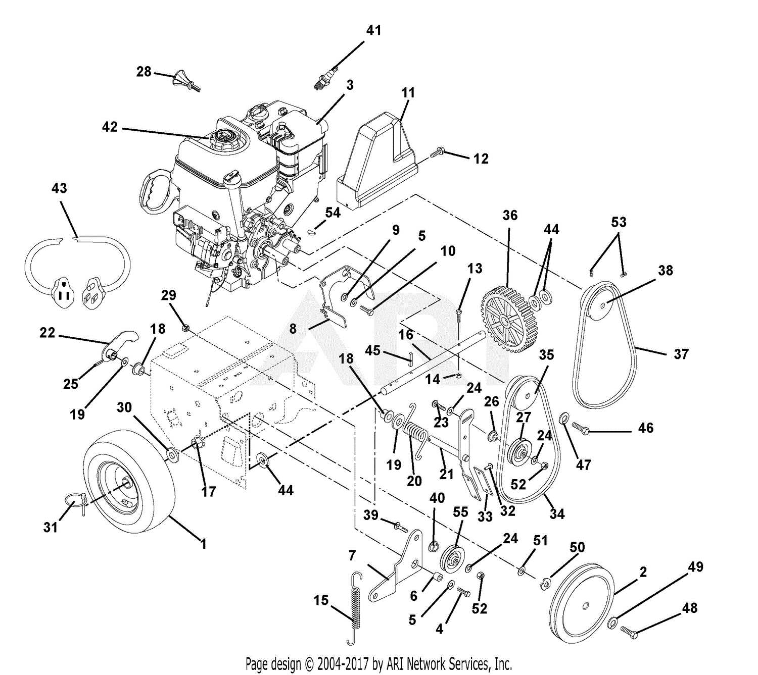
The drive belt assembly is a crucial component that ensures the efficient operation of various machinery. Identifying its location can enhance maintenance procedures and improve the overall performance of the equipment. This section will guide you through the steps necessary to locate the drive belt assembly effectively.
To find the drive belt assembly, it is important to consider the machine’s layout and the orientation of the components. Understanding how the parts interact with one another will facilitate a smoother identification process. The following table outlines the key areas to inspect when searching for the drive belt assembly:
| Inspection Area |
Description |
| Front Access Panel |
Check behind the front access panel for visibility of the belt and its tensioning mechanisms. |
| Drive Housing |
The drive housing often contains the assembly; removing this cover may be necessary for a clear view. |
| Near the Engine |
Examine the area close to the engine where power transmission typically occurs. |
| Underneath the Chassis |
In some models, the assembly is located beneath the chassis; ensure to look carefully in this space. |
Following these guidelines will aid in successfully locating the drive belt assembly, leading to more effective maintenance and operation of the machine.
Detailed View of Gearbox Components
The gearbox is a critical component of machinery, serving as the mechanism that transmits power from the engine to the drive system. Understanding its intricacies allows for better maintenance and efficient operation. This section delves into the essential parts that make up the gearbox, highlighting their functions and interrelations.
Main Components
- Input Shaft: This component receives power from the engine and begins the process of transmission.
- Output Shaft: It transfers the power to the wheels or other machinery parts, effectively driving the system.
- Gear Sets: These are crucial for altering torque and speed; different gear configurations provide various performance characteristics.
- Bearings: These support the rotating shafts, ensuring smooth operation and reducing friction.
- Seals: They prevent the leakage of lubricants and protect the internal components from contamination.
Supporting Elements
- Casing: The outer shell that houses all the components, providing structural integrity and protection.
- Lubrication System: Essential for reducing wear and heat, this system ensures all moving parts operate efficiently.
- Control Mechanism: This includes levers and sensors that allow operators to manage the gearbox settings effectively.
By familiarizing oneself with these key components, operators can enhance their understanding of the gearbox’s functionality and ensure optimal performance through regular maintenance and timely repairs.
Maintaining the Cutterbar for Optimal Performance
Proper upkeep of the cutting mechanism is essential for achieving maximum efficiency and longevity in agricultural machinery. Regular maintenance ensures that the equipment operates smoothly, preventing potential breakdowns and ensuring that crops are processed effectively. This section will explore key practices and considerations that contribute to the sustained performance of the cutterbar.
Routine Inspection is crucial in identifying wear and tear. Regularly examine the entire assembly for signs of damage or degradation. Look for loose components, cracks, or bent sections, as these issues can lead to suboptimal operation and may require immediate attention.
Sharpening the Blades is another vital aspect of maintenance. Dull blades can significantly reduce cutting efficiency and lead to uneven crop handling. It’s recommended to sharpen the blades frequently, depending on usage, to maintain a clean cut and minimize strain on the machine.
Additionally, Lubrication plays a significant role in ensuring smooth operation. Keeping the moving parts well-lubricated reduces friction and wear, enhancing the overall functionality of the cutting unit. Refer to the manufacturer’s guidelines for the appropriate lubricants and intervals.
Finally, Adjustments should be made to ensure the cutting height and angle are optimal for the specific type of crop being harvested. Proper adjustments not only improve performance but also help in preventing damage to both the machine and the crops.
In summary, maintaining the cutting assembly involves regular inspections, sharpening of blades, appropriate lubrication, and necessary adjustments. By adhering to these practices, operators can ensure their machinery remains in peak condition, resulting in improved efficiency and reduced downtime.
Identifying Electrical System Parts
The electrical system of machinery is a complex network that facilitates the operation of various components. Understanding the different elements within this system is crucial for effective troubleshooting and maintenance. By familiarizing oneself with the key parts, operators can ensure optimal performance and longevity of their equipment.
Components Overview: The electrical assembly generally includes various items such as wiring harnesses, connectors, relays, and switches. Each element plays a specific role in transmitting power and signals, making it essential to recognize their functions and interconnections.
Wiring Harnesses: These are collections of wires bundled together, designed to deliver electrical power and communication signals throughout the system. Identifying the correct wiring harness can streamline repairs and prevent miscommunication between components.
Connectors: These small yet vital parts enable the connection of different electrical elements. Understanding the types of connectors and their placements is key for effective assembly and disassembly, ensuring that electrical pathways remain intact.
Relays and Switches: These components control the flow of electricity within the system. Recognizing their locations and functions allows for quicker diagnostics and facilitates easier replacements when needed.
In summary, a comprehensive understanding of the electrical components is indispensable for maintaining efficient machinery operation. Familiarity with each part’s role contributes to effective problem-solving and enhances overall equipment reliability.
Finding Replacement Parts for Obsolete Components
In the realm of machinery maintenance, sourcing substitutes for outdated elements can pose significant challenges. As equipment ages, certain components may become difficult to find due to production discontinuation or scarcity in the market. However, with the right approach and resources, one can successfully navigate this obstacle and ensure the continued functionality of their equipment.
Identifying Suitable Alternatives
When original components are no longer available, it is essential to explore alternative solutions. Here are some strategies to consider:
- Consult Manufacturer Resources: Reach out to the original equipment maker for recommendations on compatible substitutes.
- Engage with Industry Forums: Online communities often share insights on where to find hard-to-locate components.
- Local Dealers and Distributors: Building relationships with local suppliers may reveal hidden stock or special orders.
Utilizing Custom Fabrication
In cases where no substitutes are available, custom fabrication can be an effective solution. Consider the following options:
- 3D Printing: This modern technology allows for the creation of complex shapes and designs tailored to specific needs.
- Machine Shops: Local workshops may have the capability to manufacture bespoke replacements based on your specifications.
- Engineering Consultations: Hiring an expert can assist in identifying potential solutions and ensuring the integrity of the design.
By employing these methods, it is possible to extend the lifespan of your machinery and maintain its operational efficiency, even when faced with the challenge of obsolete components.
Preventive Maintenance Tips for Longevity
Ensuring the durability and efficiency of your equipment is essential for maximizing productivity and minimizing unexpected downtime. Regular maintenance not only extends the lifespan of machinery but also enhances its performance. This section provides practical strategies that can be easily implemented to promote optimal functionality over time.
Routine Inspections
Conducting systematic evaluations of machinery can help identify potential issues before they escalate. Regular checks allow operators to catch wear and tear early, ensuring that all components function as intended.
Lubrication and Cleaning
Maintaining cleanliness and proper lubrication is vital for the smooth operation of moving parts. Dirt and debris can cause friction and wear, while adequate lubrication reduces heat and extends component life.
| Maintenance Task |
Frequency |
Benefits |
| Inspect belts and hoses |
Monthly |
Prevents failures and enhances safety |
| Change oil and filters |
Every 500 hours |
Improves efficiency and reduces wear |
| Check fluid levels |
Weekly |
Ensures optimal operation |
| Clean air filters |
Every 100 hours |
Enhances air quality and performance |
|
