When creating detailed visual representations of construction projects, it is crucial to break down the components involved into smaller, organized sections. This approach allows for a better comprehension of how individual elements come together to form a cohesive structure. Through the use of simple schematics, even complex configurations can be understood with ease.
The layout typically emphasizes the relationship between different structural units. By highlighting connections and alignment, these visuals offer a clear insight into the assembly process and functional purpose. Properly reading and interpreting such visuals ensures a smooth workflow, preventing misunderstandings during the project execution phase.
Focusing on the arrangement and structure of specific units within the visual helps to map out practical considerations, such as placement, support, and reinforcement. This method contributes to the overall integrity of the design, ensuring it meets both aesthetic and practical standards.
Understanding the Elements of a Fence Diagram
Visual representations of structures can simplify complex data, allowing for easier interpretation. These illustrations organize layers of information in a way that highlights relationships and spatial patterns, providing valuable insights into the overall layout and function. By analyzing each component, you can decode how various sections interact and contribute to the whole.
Key Sections and Their Role
Each segment within the visual layout serves a specific purpose. The arrangement of these segments reflects the distribution and connections between elements. This organization helps to clarify how different areas align with one another, creating a cohesive representation.
Interpreting the Spatial Relationships
Understanding the positioning and spacing between various sections is essential for extracting meaningful information. These spatial cues offer clues about hierarchical importance, flow, and the boundaries of each area. By focusing on these details, you can draw more accurate conclusions from the visual representation.
Components of a Structural Boundary Representation
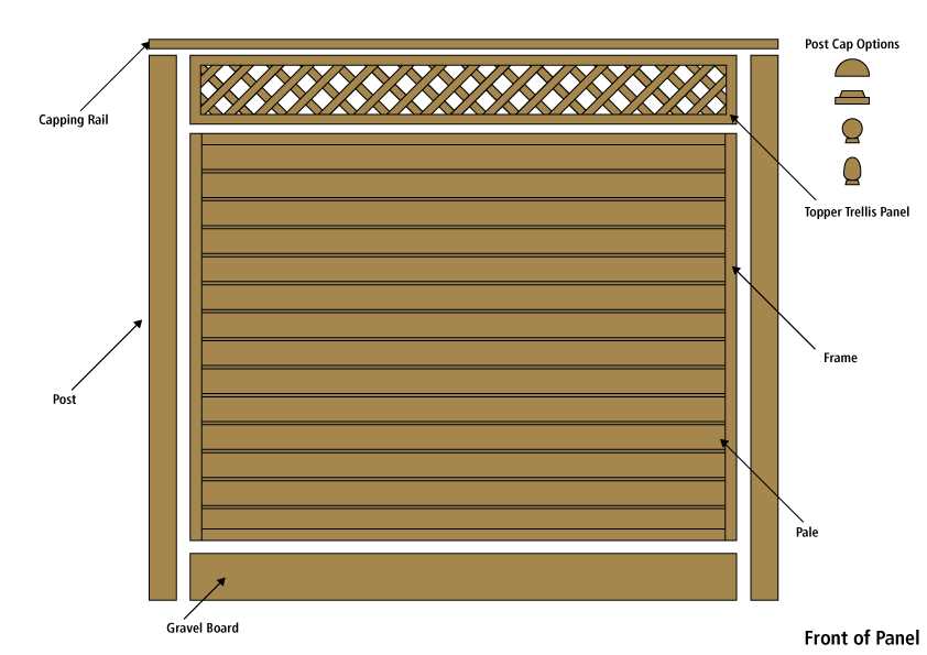
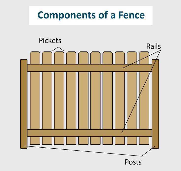
A structural boundary serves as a vital element in defining and organizing the separation between different areas or zones. The configuration of this boundary involves multiple key elements that work together to provide stability, security, and aesthetic appeal. Understanding these components is essential for designing effective and lasting structures.
Support Framework: The foundation of the boundary is built upon a solid support framework. These are the vertical and horizontal elements that ensure strength and resilience, holding the structure in place under various conditions.
Horizontal Elements: Acting as connectors, horizontal elements link the support framework together, ensuring consistency and alignment. They also enhance the overall stability by distributing pressure evenly across the structure.
Infill Sections: These are the central sections designed to fill the space between the supports. Whether for privacy, decoration, or practical purposes, the infill contributes to the overall purpose and function of the boundary.
Fixing Elements: Anchoring the structure firmly to the ground or base, fixing elements are essential to prevent shifting or instability over time. These components provide critical security and long-term durability.
Finishing Components: To complete the boundary’s appearance and provide additional protection, finishing components are often applied. These can include decorative elements or protective layers that enhance both functionality and visual appeal.
Visualizing Topographical Data in Fencing Models
In various fields, understanding the three-dimensional structure of terrain is crucial. Specialized models are commonly employed to represent geographic features and allow for more intuitive interpretation of data. These models offer a way to visualize spatial relationships and elevation changes in a clear and organized manner.
Key Elements of Topographical Representation
- Contours: Contours are lines connecting points of equal elevation. They help illustrate the slopes and elevations of a landscape.
- Grids: Grids divide the area into uniform sections, making it easier to interpret specific locations and their respective elevations.
- Markers: These indicate specific landmarks or key points, such as peaks or valleys, that are important for analysis.
Benefits of Using Models for Terrain Visualization
Utilizing structured visual models offers several advantages in analyzing and interpreting complex terrains:
- Improved accuracy in visualizing elevation changes across wide areas.
- Clear representation of spatial relationships between different geographic features.
- Enhanced ability to predict water flow, land usability, or planning for construction projects.
Key Segments in Geologic Fencing Diagrams
Geological cross-sections are valuable tools in understanding the structure of the Earth’s subsurface. They help interpret the distribution of different layers and materials below the surface, allowing for a comprehensive view of the underlying geology. These models enable experts to visualize the arrangement and relationships between various geological formations.
Vertical Profiles
One of the essential elements involves representing the vertical alignment of geological formations. By analyzing vertical profiles, geologists can trace the positioning of strata, faults, and rock units at different depths, offering insights into the subsurface’s physical structure. Vertical profiles often provide information on rock type, formation thickness, and potential resource locations.
Connections Between Layers
The second important aspect is the interaction between different geological layers. These connections reveal how layers have shifted, been deformed, or eroded over time. Studying these intersections allows for a deeper understanding of historical events, such as tectonic movements or sedimentary processes.
| Segment | Purpose | |
|---|---|---|
| Vertical Profiles | Show the arrangement and depth of geological formations. |
| Element | Description | Integration Method |
|---|---|---|
| Boundary Lines | Define limits and sections within the visual representation. | Layering and Color Coding |
| Data Points | Specific locations that hold relevant information. | Symbolization and Annotation |
| Connections | Show relationships between different elements. | Line Styling and Arrows |
| Legends | Provide keys to interpret symbols and colors. | Standardized Notations |
Ultimately, the effectiveness of visual boundaries lies in their ability to integrate various data points in a manner that enhances comprehension and utility. By following systematic integration practices, stakeholders can derive valuable insights and make informed decisions based on the visualized information.
Common Applications of Fence Diagrams in Geology
Visual representations play a crucial role in understanding geological structures and processes. These illustrations facilitate the communication of complex subsurface conditions, allowing geologists to analyze and interpret data more effectively. By presenting various layers and features, they enable a clearer understanding of geological formations, which is essential for various applications in the field.
Resource Exploration
In the context of resource exploration, such as mining or oil extraction, these visual tools help identify potential reserves. By showcasing the arrangement of different strata, they assist in assessing the economic viability of extracting natural resources. Geologists can pinpoint areas of interest, making informed decisions regarding exploration efforts.
Environmental Studies
In environmental geology, such representations are instrumental in studying groundwater flow and contamination. They provide insights into the relationships between different geological units, allowing for better management of water resources and the assessment of environmental risks. By illustrating how pollutants might migrate through various layers, these visuals aid in developing effective remediation strategies.
Linearity and Flow in Diagrammatic Fences
When illustrating boundaries and divisions, the arrangement of elements plays a crucial role in conveying structure and meaning. A coherent flow ensures that viewers can easily navigate through the presented information, leading to a better understanding of the overall framework. This aspect of design not only enhances visual appeal but also aids in effective communication.
Understanding Continuity
Continuity refers to the seamless connection between different components within the framework. It helps create a narrative that guides the observer’s eye, fostering a logical progression from one segment to the next. Achieving this harmony involves careful consideration of spacing, alignment, and proportionality, which together contribute to a unified visual experience.
Utilizing Directional Cues
Directional cues are instrumental in establishing a path for interpretation. By strategically placing elements and employing lines or arrows, creators can direct attention and influence the viewer’s journey through the layout. This intentional guidance promotes clarity and ensures that the essential ideas are not lost in the complexity of the structure.
| Element | Function |
|---|---|
| Lines | Indicate connections and relationships |
| Shapes | Define areas and boundaries |
| Colors | Enhance visual distinction and appeal |
| Text | Provide context and explanations |
3D Projection and Spatial Relationships in Fences

Understanding the three-dimensional representation and the interactions between various elements is essential in creating effective boundary structures. This perspective allows for a comprehensive view of how each component contributes to the overall integrity and functionality of the enclosure. By analyzing the spatial dynamics, designers can enhance both aesthetic appeal and practical performance.
Three-dimensional visualization plays a crucial role in the planning process. It enables stakeholders to see how different components relate to each other in a physical space, ensuring that proportions, alignments, and placements are optimized. This approach helps in identifying potential issues before actual construction begins, reducing costs and time delays.
Furthermore, understanding spatial relationships aids in assessing environmental factors. Considerations such as sunlight, wind direction, and surrounding landscapes can influence the design choices. By integrating these elements into the overall strategy, one can achieve a harmonious balance between functionality and visual coherence, resulting in a robust and attractive perimeter solution.
Enhancing Geological Understanding with Fence Models

Visual representations play a crucial role in deepening our comprehension of subsurface formations and their intricate relationships. By utilizing specific structural illustrations, geologists can effectively convey complex data, making it accessible and interpretable for various applications, from resource exploration to environmental studies.
The Importance of Visual Representation
Utilizing structured visual tools provides several benefits in geological analysis:
- Clarity: These models simplify the representation of three-dimensional geological structures, allowing for a clearer understanding of spatial relationships.
- Comparison: By juxtaposing different geological formations, it becomes easier to identify similarities and differences, enhancing analytical capabilities.
- Interpretation: These visualizations assist in interpreting geological data, aiding in decision-making processes for exploration and land use.
Applications in Geoscience
The use of structured illustrations in geology extends to various applications:
- Resource Management: These models facilitate the identification and management of natural resources, such as minerals and hydrocarbons.
- Environmental Studies: Understanding subsurface conditions is critical for assessing environmental impacts and planning remediation efforts.
- Urban Planning: Accurate geological representations inform infrastructure development and land-use planning, minimizing risks associated with geological hazards.
