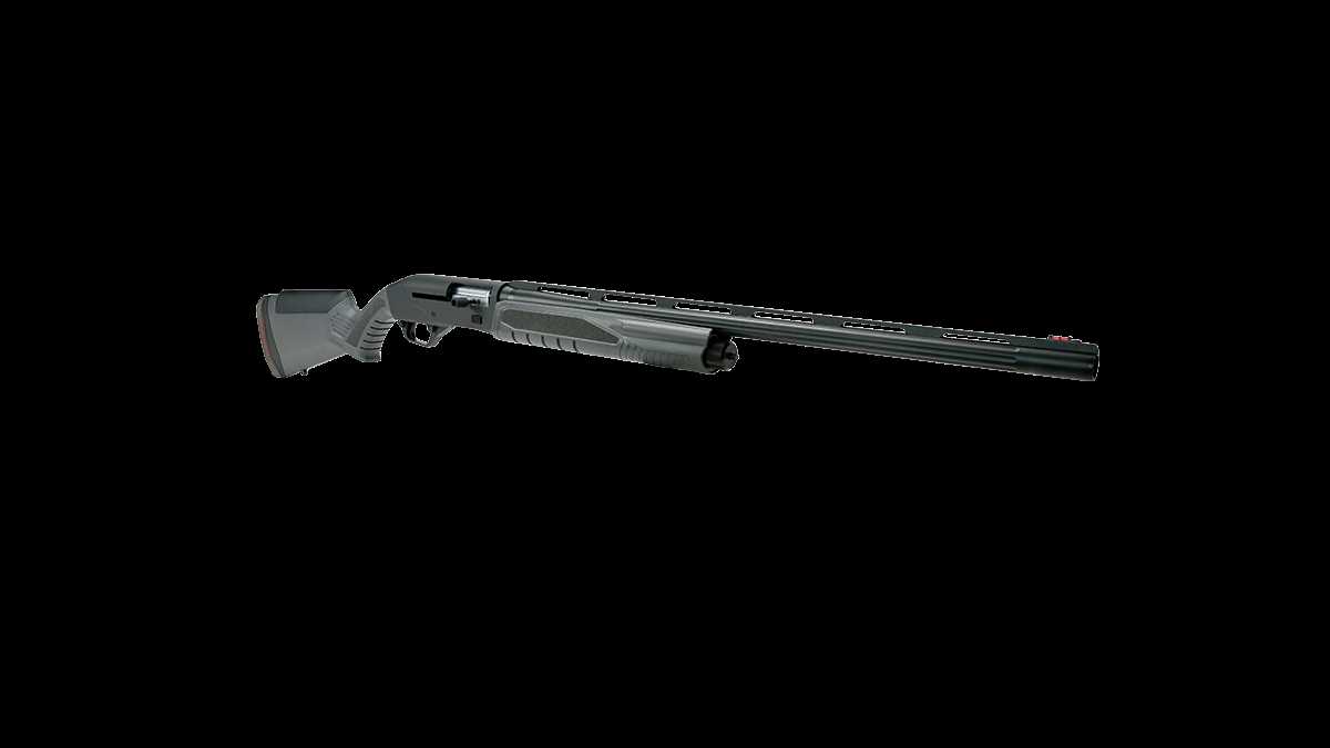
Understanding how the various elements of a firearm work together is essential for maintaining its reliability and performance. This guide provides a comprehensive look at the internal and external elements that contribute to the overall functionality of this particular model. Whether you are an enthusiast or a professional, having a clear picture of each mechanism can be invaluable for repairs or modifications.
Each component plays a crucial role in ensuring the weapon operates smoothly. From the internal mechanisms to the outer assemblies, all parts work in unison to deliver consistent performance. In this breakdown, we’ll examine the key elements that make up this firearm, offering detailed descriptions and insights into their specific functions.
By dissecting the individual components, we aim to provide you with a clearer understanding of how they contribute to the overall system. This knowledge can help in troubleshooting issues, replacing worn-out elements, or simply gaining a better appreciation of the engineering involved.
Savage 64 Exploded View Overview
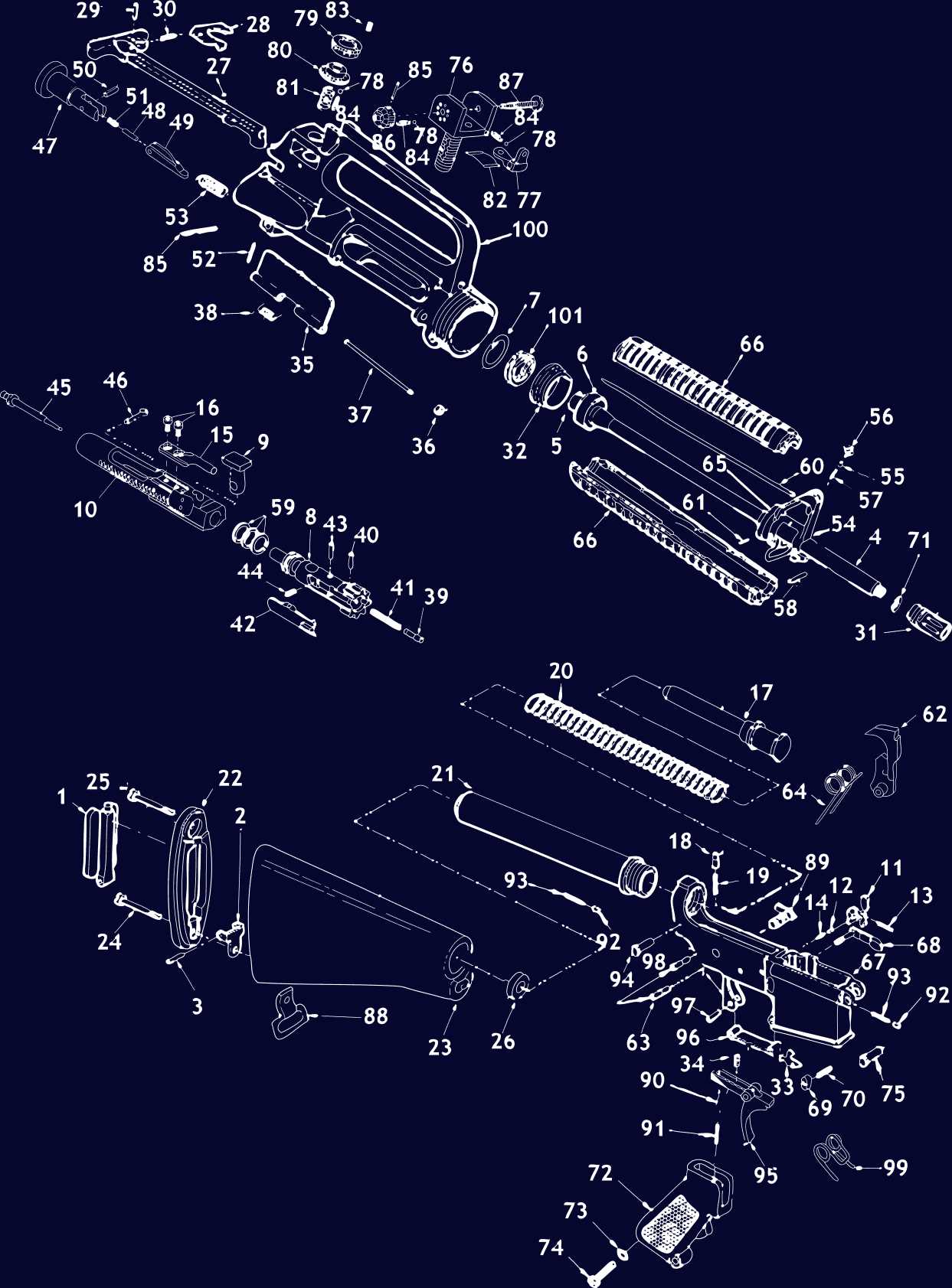
The visual breakdown of this firearm offers a clear representation of its internal and external components. By examining the individual elements in detail, users can gain an understanding of how each part interacts within the overall structure.
- Trigger mechanism assembly
- Barrel and receiver alignment
- Stock attachment and fitting
- Internal spring positioning
- Magazine placement and feeding system
This detailed view allows for easier identification of potential malfunctions and aids in maintenance or upgrades, ensuring the firearm operates smoothly.
Key Components of the Savage 64
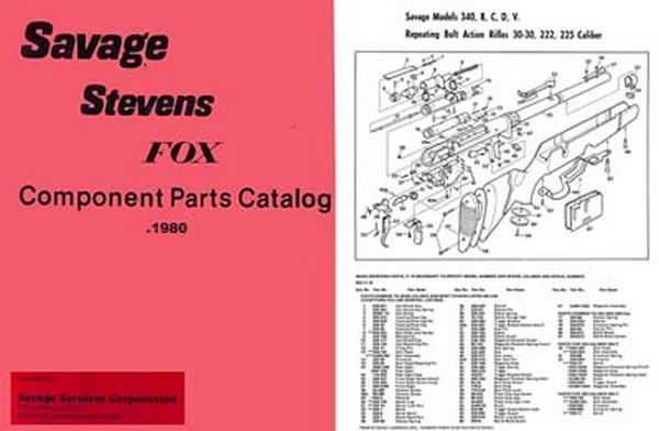
The structure of this model consists of several essential elements that contribute to its overall functionality. These elements work together to ensure reliable performance and precise operation, forming a cohesive system that delivers accurate results during use.
Main Functional Elements
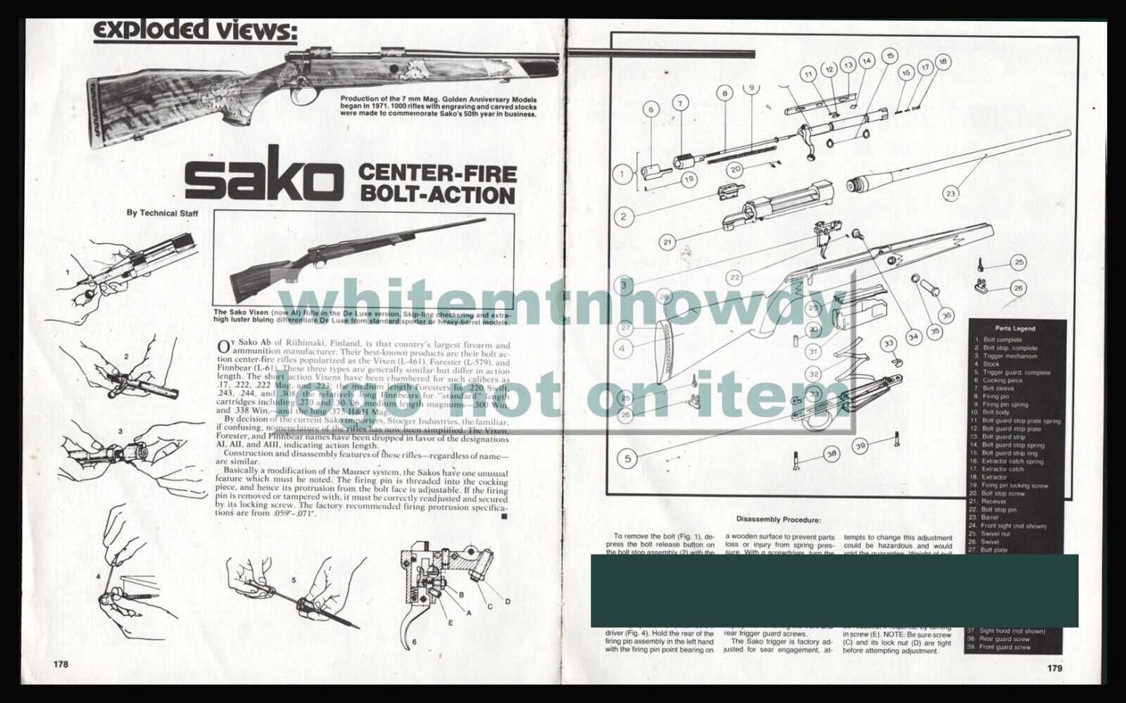
- Receiver assembly, which houses critical moving parts and provides the framework for operation.
- Barrel, designed to guide and project the round accurately.
- Trigger mechanism, allowing the user to control the firing action with precision.
- Safety features, incorporated to prevent accidental discharge and enhance user safety.
Additional Features
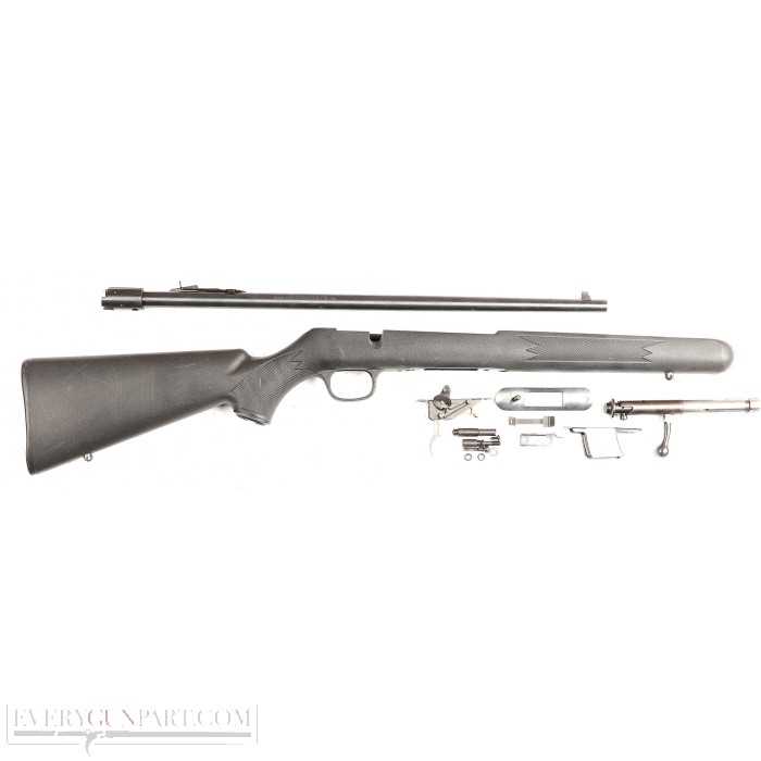
- Stock, providing a comfortable and stable grip for the user.
- Barrel and Receiver Assembly Breakdown
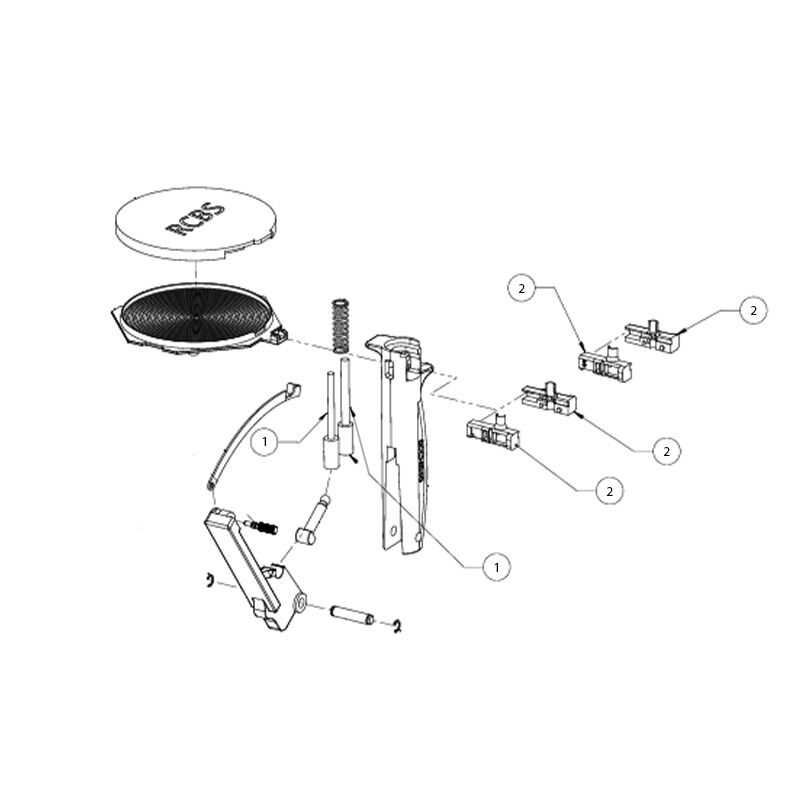
The intricate relationship between the barrel and receiver is crucial for the overall function of a firearm. Understanding how these components interact can offer insights into maintenance and troubleshooting. The alignment, secure connection, and precise engineering of these two elements play a vital role in ensuring optimal performance and safety.
The barrel houses the projectile’s path, while the receiver provides support and stability. Disassembling these key components reveals how they are structured to work seamlessly together. Each piece has a specific function, contributing to the reliability and accuracy of the mechanism.
Trigger Mechanism and Safety Features
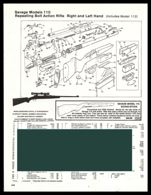
The firing system and protective elements of this firearm are crucial for ensuring both performance and user safety. Understanding the interaction between these components helps in maintaining reliable operation during use.
The firing mechanism is designed to provide consistent and smooth operation, with a focus on minimizing accidental discharge. Several key elements play a role in its functionality:
- Trigger pull: The force required to activate the firing sequence, engineered for balance between ease of use and safety.
- Seer and hammer: Key components that interact to release the firing pin, controlled by the trigger motion.
- Trigger reset: Allows the system to return to a ready position after each shot, ensuring quick follow-up shots.
For added protection, various safety features are implemented:
- Manual safety switch
Stock and Mounting Points Identification
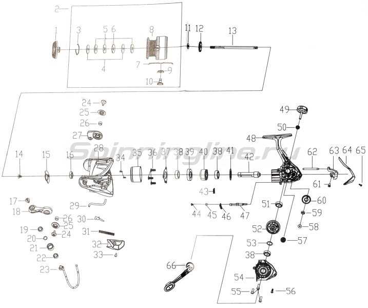
The structural framework and attachment points are crucial for ensuring stability and proper alignment in a firearm. Recognizing these areas is key to understanding how the components are integrated and secured for optimal performance.
Component Mounting Point Location Purpose Buttstock Rear section Provides shoulder support and stability Receiver Central area Houses the firing mechanism Barrel Front section Guides the bullet and impacts accuracy Forearm Under the barrel Magazine and Feeding System Layout
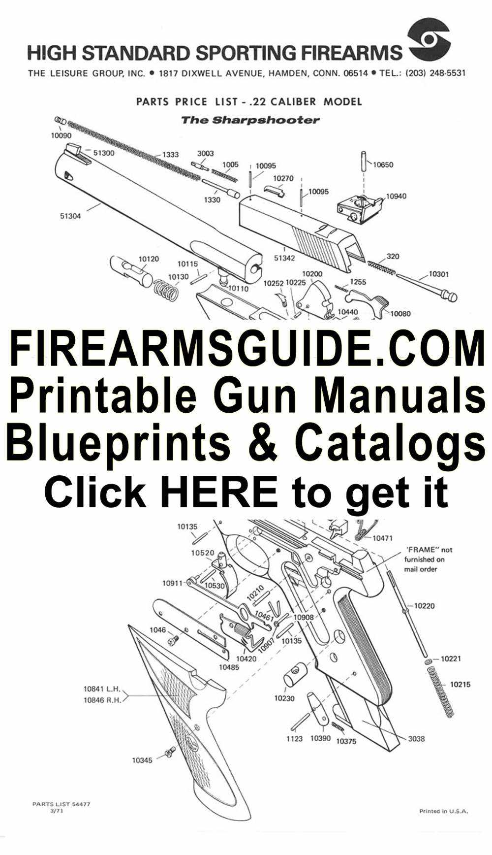
The arrangement of the ammunition storage and feeding mechanism is crucial for the efficient operation of any firearm. This system ensures a reliable supply of rounds to the chamber, enabling smooth firing cycles. Understanding its configuration can help users maintain optimal performance and troubleshoot potential issues.
The key components of the ammunition storage and feeding system include:
- Magazine: The container that holds the cartridges, designed for quick loading and reloading.
- Follower: A component that pushes the cartridges upward as they are fed into the chamber.
- Spring: Provides the necessary force to keep the cartridges in position and assist the follower.
- Feed Lips: The part of the magazine that guides the cartridges into the chamber during cycling.
To ensure proper functionality, it is essential to pay attention to the following aspects:
- Loading: Ensure that the magazine is filled according to the manufacturer’s specifications to avoid malfunctions.
- Inspection: Regularly check the magazine for wear, dirt, or damage that may impede performance.
- Lubrication: Apply appropriate lubricants to moving parts to ensure smooth operation.
Understanding the layout and function of the ammunition storage and feeding system is vital for anyone looking to enhance their knowledge of firearm mechanics and ensure reliable operation during use.
Fire Control Group Detailed Analysis
The fire control assembly is a crucial component that dictates the operation and reliability of a firearm. It encompasses various elements that work together to facilitate the discharge mechanism, ensuring efficient and safe firing. Understanding the intricate functions and relationships between these components is essential for both maintenance and performance enhancement.
Key Components and Their Functions
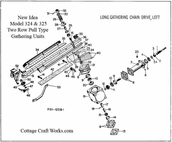
This assembly includes several critical elements, each playing a distinct role. The trigger mechanism is responsible for initiating the firing sequence, while the sear ensures proper engagement and release of the firing pin. Additionally, the disconnector serves to prevent accidental discharges by interrupting the firing cycle during cycling.
Maintenance and Troubleshooting Considerations
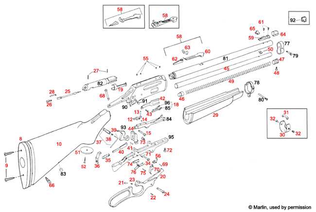
Regular inspection and maintenance of the fire control assembly are vital for optimal performance. Users should pay attention to wear and tear on components, as even minor defects can lead to significant operational issues. Identifying and addressing these concerns early can greatly enhance the firearm’s longevity and reliability. Furthermore, understanding the assembly’s intricacies allows for more effective troubleshooting when malfunctions arise.
Bolt Assembly and Functioning Parts
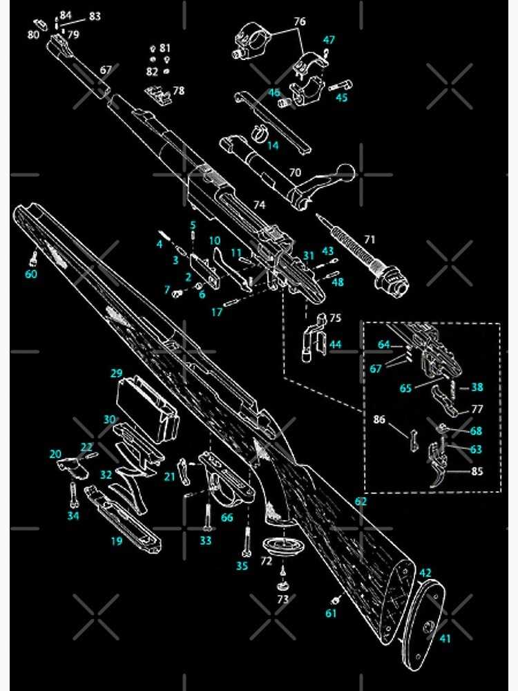
The bolt assembly is a critical component in the operation of a firearm, playing a vital role in the firing mechanism and overall functionality. This assembly ensures that ammunition is securely fed, fired, and ejected efficiently, contributing to the reliability and performance of the weapon.
Components of the Bolt Assembly
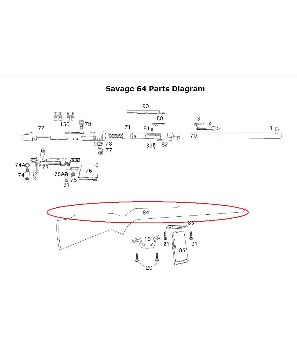
Understanding the various elements that make up the bolt assembly can help users appreciate its complexity and importance. The key components include:
- Bolt Body
- Firing Pin
- Extractor
- Ejector
- Locking Lugs
- Spring Mechanisms
Functionality Overview
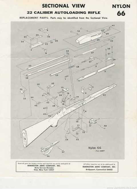
Each component plays a distinct role in the operation of the bolt assembly:
- Feeding: The bolt moves forward to chamber a round from the magazine.
- Locking: Locking lugs engage to secure the bolt in place during firing.
- Firing: The firing pin strikes the primer, igniting the propellant.
- Ejecting: The extractor pulls the spent casing from the chamber.
- Resetting: The assembly returns to its initial position, ready for the next cycle.
Sights and Optic Mounting Configuration
The configuration of aiming devices and optical attachments plays a critical role in enhancing accuracy and user experience. Proper alignment and secure mounting are essential for achieving optimal performance. This section delves into the various aspects of integrating these components to ensure precise targeting and effective usage.
Types of Sights
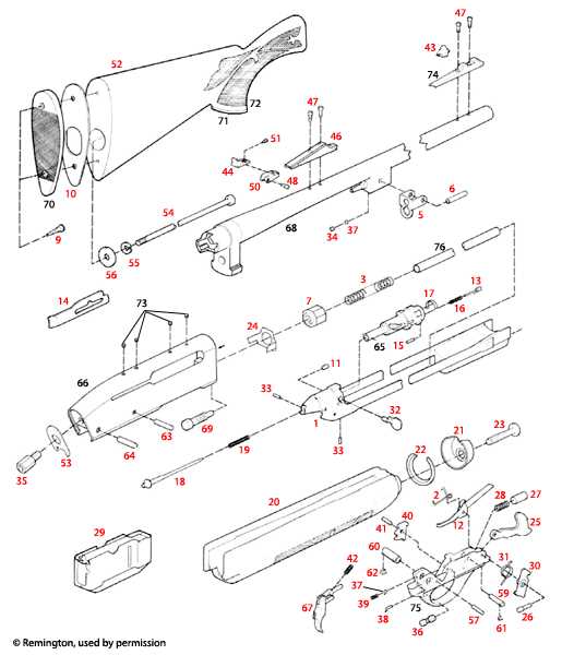
There are several types of aiming systems available, each designed to meet specific needs. Traditional iron sights offer a straightforward approach, while modern optics, such as red dot sights and scopes, provide enhanced visibility and target acquisition. Selecting the right type depends on the intended application, whether for hunting, competitive shooting, or tactical scenarios.
Mounting Techniques
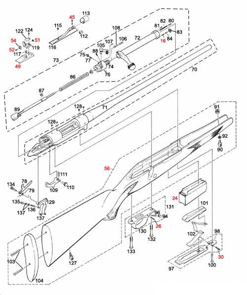
Securing optics to a firearm involves various mounting techniques that ensure stability and repeatability. Picatinny and Weaver rails are popular choices, providing versatility in adjusting positioning. It is crucial to select compatible mounts and ensure they are tightly fastened to prevent any movement during use. Periodic checks of these connections can help maintain accuracy over time.
Disassembly of Savage 64 Internal Parts
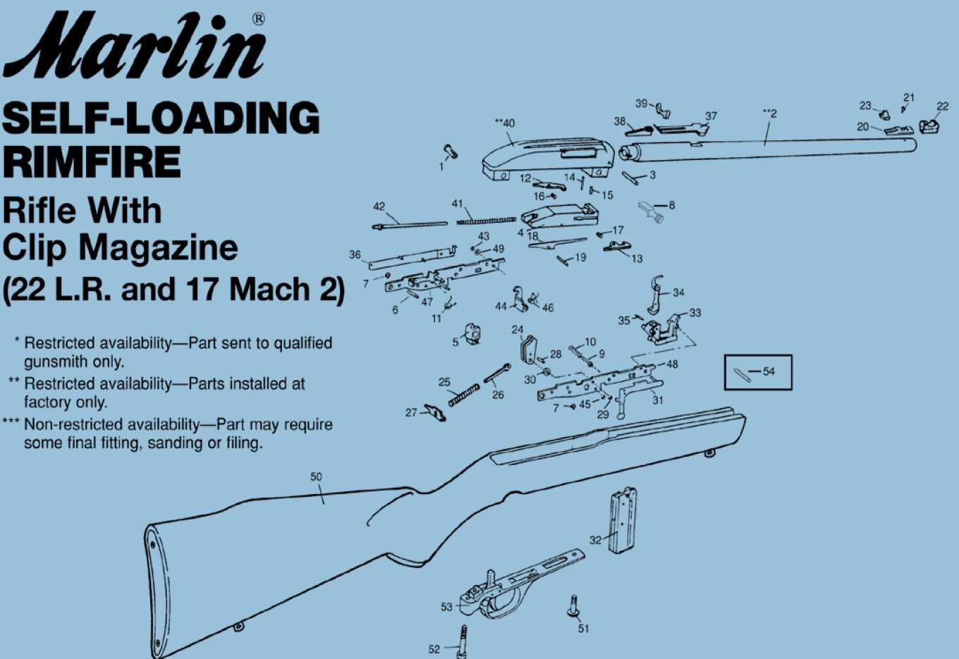
This section provides a comprehensive guide to the process of dismantling the internal components of a specific firearm model. Understanding the intricate mechanisms within the assembly is essential for maintenance, troubleshooting, and customization.
Before starting the disassembly process, gather the necessary tools and prepare a clean workspace. The following steps outline the recommended procedure:
- Ensure the firearm is unloaded and safe to handle.
- Remove the outer casing by unscrewing the designated screws.
- Carefully detach the trigger mechanism and related components.
- Take out the bolt assembly, noting the orientation for reassembly.
- Extract the recoil spring and any additional internal elements.
During disassembly, pay close attention to the arrangement and condition of each component. Keeping a detailed record or taking photos can aid in the reassembly process.
After completing the dismantling, inspect each piece for wear and damage, ensuring everything is in optimal condition for reinstallation.
Maintenance Tips for Savage 64 Components
Proper upkeep of firearm elements is crucial for ensuring optimal performance and longevity. Regular maintenance not only enhances reliability but also contributes to safety and accuracy. Adopting a systematic approach to care can help identify potential issues before they escalate, ultimately extending the life of your equipment.
Regular Inspection Procedures
Conducting routine checks is essential for maintaining the functionality of various components. Look for signs of wear, corrosion, or damage that may affect operation. Here are some key areas to focus on during inspections:
Component Inspection Focus Recommended Action Barrel Look for rust and obstructions Clean and lubricate as needed Trigger Assembly Check for smooth operation Replace springs if necessary Stock Inspect for cracks or warping Refinish or replace damaged parts Cleaning and Lubrication Guidelines
Cleaning and applying appropriate lubricants are fundamental steps in maintenance. Use high-quality cleaning solutions and oils designed for firearms. Follow these tips for effective cleaning:
- Always disassemble components according to the manufacturer’s guidelines.
- Use a soft brush to remove debris from hard-to-reach areas.
- Apply lubricant sparingly to moving parts to prevent buildup.