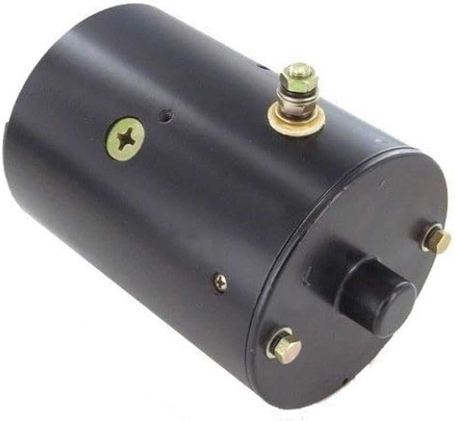
The world of fluid control mechanisms is intricate and essential across many industries. From construction to agriculture, these systems play a vital role in ensuring smooth operations. However, understanding how these setups work, especially their inner workings, can be quite complex. This section aims to break down the fundamental elements that compose these systems, providing clarity for those looking to enhance their knowledge.
Key mechanisms within fluid management systems consist of a variety of interconnected components. These elements work in harmony to convert energy into movement, powering various functions that are essential in different applications. By gaining insight into how these pieces interact, one can better maintain and troubleshoot the system.
In this breakdown, we will examine a detailed schematic, allowing users to familiarize themselves with the essential elements, their placement, and their purpose. Understanding these details is crucial for ensuring efficient operation and longevity of the entire setup.
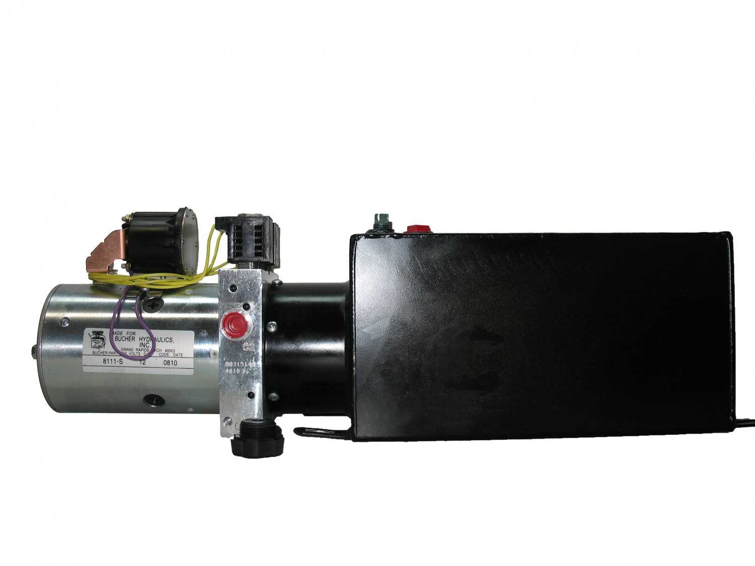
Monarch 8111-S Hydraulic Pump Overview
This section provides a detailed overview of one of the most reliable and efficient solutions for various fluid control systems. Known for its robust design and ability to manage high-pressure applications, this model is frequently used in industrial and commercial settings where performance and reliability are critical.
Key Features
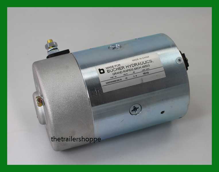
- Durable construction suited for demanding environments
- Engineered to handle intense operational pressures
- Compact design, making it ideal for space-limited installations
- Highly efficient in terms of power-to-output ratio
Applications and Uses
Widely employed across various industries, this model excels in systems that require reliable fluid movement and control. Its versatility allows it to be integrated into a range of equipment, from mobile systems to large-scale industrial machinery.
- Material handling equipment
- Automated machinery
- Power transmission systems
Key Components of the Monarch 8111-S
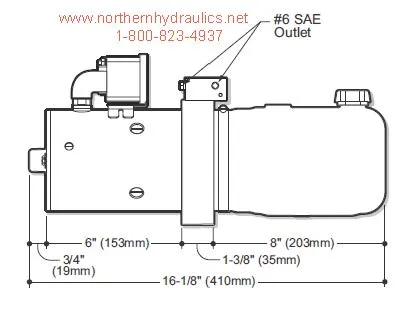
This section will explore the essential elements that contribute to the functionality and efficiency of this specific model. Understanding the core features and mechanisms behind its operation will help identify maintenance needs and improve overall performance.
Main Structure
The primary frame is constructed from durable materials, designed to support all internal components. Its robust design ensures longevity and reliable operation, even in demanding conditions. The outer shell also plays a crucial role in protecting sensitive internal parts from environmental damage.
Internal Mechanisms
At the core, this system relies on a combination of mechanical and fluid components to create seamless energy conversion. Various seals, valves, and connectors ensure a smooth flow, controlling the pressure and flow rates required for effective functionality. The interaction between these parts is crucial for maintaining optimal performance.
| Component | Function | ||||||||||
|---|---|---|---|---|---|---|---|---|---|---|---|
| Frame Assembly | Supports and protects internal elements. | ||||||||||
| Valves | Regulate the flow of energy and fluid through the system. |
| Component | Function | ||||||||||
|---|---|---|---|---|---|---|---|---|---|---|---|
| Reservoir | Stores the fluid required for energy transfer. | ||||||||||
| Valves | Regulate the direction and flow of energy within the system. |
| Component | Function |
|---|---|
| Microcontroller | Processes input signals and executes control algorithms. |
| Sensor Module | Monitors system parameters such as pressure and temperature. |
| Actuator Interface | Translates control signals into physical actions, adjusting flow and pressure. |
| Power Supply | Provides the necessary energy for operation and ensures stability. |
Each component within the control unit contributes to the overall functionality, highlighting the importance of regular maintenance and troubleshooting. By understanding how these elements interact, users can enhance the performance and longevity of the entire system.
Fluid Pathways and Connections
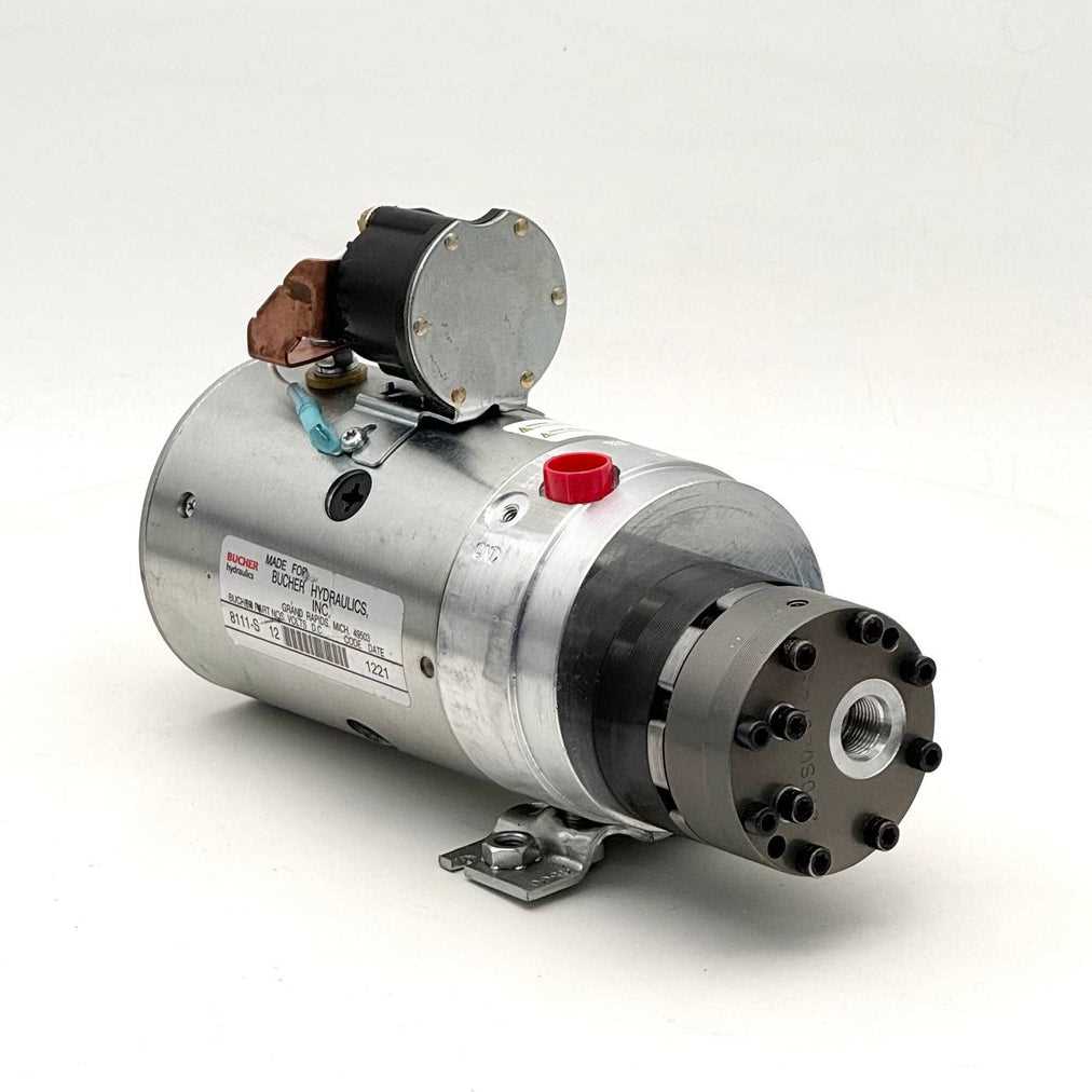
The movement of fluids within a system is crucial for its efficiency and performance. Understanding how these pathways are structured and interconnected can greatly enhance troubleshooting and maintenance efforts. Proper management of fluid flow ensures that every component functions as intended, leading to optimal results in various applications.
Key Components of Fluid Circulation
- Tubing: Acts as the primary channel for fluid transport, facilitating movement between different sections of the system.
- Valves: Control the flow direction and pressure, allowing for effective regulation of the system’s operation.
- Connectors: Essential for joining different parts, ensuring a secure and leak-proof assembly.
- Filters: Maintain fluid purity by removing contaminants, thereby prolonging the lifespan of components.
Flow Management Techniques
- Ensure all connections are tight and free from wear to prevent leaks.
- Regularly inspect filters and replace them as needed to maintain optimal flow.
- Utilize valves strategically to manage pressure and fluid distribution effectively.
- Monitor tubing for any signs of wear or damage, replacing sections as necessary.
By focusing on these elements, operators can significantly enhance the reliability and functionality of the entire system, leading to improved performance and reduced downtime.
Pump Housing and Structural Features
The casing of a hydraulic device plays a crucial role in ensuring its efficiency and durability. This structural component is designed to withstand high pressure and provide a secure environment for the internal mechanisms. Understanding its features is essential for maintenance and optimization.
Key Characteristics of the Casing
- Material Composition: Typically made from robust materials like cast iron or aluminum alloys, these substances are selected for their strength and resistance to wear.
- Sealing Mechanisms: Effective seals prevent leaks and maintain internal pressure, enhancing the overall performance.
- Mounting Points: Strategically placed points allow for secure attachment to other machinery, ensuring stability during operation.
Structural Design Aspects
- Flow Path Design: Optimized pathways within the casing enhance fluid dynamics, contributing to improved efficiency.
- Cooling Features: Integrated cooling fins or channels may be included to dissipate heat generated during operation, prolonging the life of internal components.
- Accessibility: Thoughtful design ensures easy access to internal parts for routine maintenance and repairs, minimizing downtime.
Electrical Wiring and Circuit Details
This section delves into the intricate aspects of electrical connections and circuitry within the system. Understanding these elements is crucial for ensuring efficient operation and reliable performance. Proper wiring practices enhance safety and functionality, while detailed circuit designs contribute to the seamless integration of components.
Each connection serves a specific purpose, and adhering to the correct specifications is essential for optimal performance. Wiring diagrams outline the necessary pathways for current flow, illustrating how various elements interact. Color coding is often employed to distinguish between different wires, simplifying troubleshooting and maintenance efforts.
Additionally, circuit details encompass the use of appropriate connectors and terminals, which play a vital role in establishing secure and effective electrical links. Regular inspections of these connections can prevent failures and ensure longevity. Understanding the layout and functionality of the circuits aids technicians in diagnosing issues and implementing necessary repairs.
Troubleshooting Common Issues in 8111-S
Addressing typical challenges encountered with hydraulic systems requires a systematic approach. By identifying symptoms and applying appropriate solutions, users can restore functionality efficiently. This section highlights prevalent problems and offers guidance on resolving them.
1. Low Pressure Output
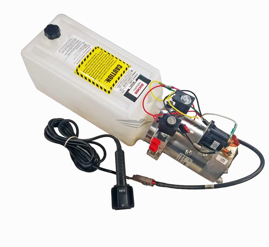
One of the most common issues is insufficient pressure. This can result in poor performance and reduced effectiveness. Follow these steps to troubleshoot:
- Check for any leaks in the system, as they can cause pressure drops.
- Inspect the fluid level to ensure it meets operational requirements.
- Examine filters for blockages that may restrict flow.
- Verify that all connections are secure and free of obstructions.
2. Unusual Noises
Unwanted sounds during operation can indicate underlying problems. Common noise issues include whining, grinding, or clattering. To diagnose:
- Listen carefully to determine the source of the noise.
- Check for loose components that may need tightening.
- Inspect bearings and seals for wear or damage.
- Ensure that the system is filled with the correct fluid type.
Maintenance Tips for Monarch 8111-S Pump
Ensuring the longevity and optimal performance of your equipment requires regular upkeep and attention. Implementing a systematic maintenance routine not only prevents unexpected failures but also enhances operational efficiency. The following guidelines will help you keep your machinery in excellent condition, allowing for smooth and reliable functionality.
Regular Inspection and Cleaning
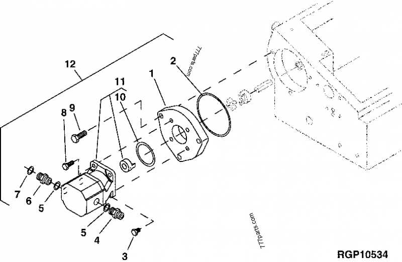
Perform frequent inspections to identify any signs of wear or damage. Pay close attention to seals, fittings, and other critical components. Cleaning the exterior and interior areas can prevent the accumulation of debris, which may hinder performance. Use appropriate cleaning agents to avoid damaging sensitive parts.
Fluid Replacement and Monitoring
Maintaining the correct fluid levels is vital for the efficient operation of your system. Regularly check the condition of the hydraulic fluid and replace it according to the manufacturer’s recommendations. Monitor for contaminants and ensure that the fluid is free of moisture, as this can significantly impact performance and lead to premature wear.
By following these maintenance tips, you can ensure the reliability and efficiency of your equipment, minimizing downtime and maximizing productivity.
