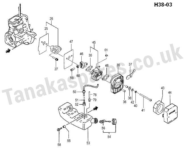
Maintaining and servicing outdoor machinery requires a solid grasp of its internal configuration. Recognizing how each element interacts with others is crucial for ensuring the device functions optimally. This knowledge helps with troubleshooting, repairs, and general upkeep, enabling users to keep the equipment running smoothly for extended periods.
Each mechanical assembly is composed of various interconnected elements that work together to achieve specific tasks. By understanding the layout and the role of each piece, users can gain insight into how to address common operational issues. Having a visual reference, such as a detailed schematic, can greatly simplify the maintenance process.
In this guide, we will explore the structural makeup of a popular outdoor device, delving into its individual elements and their respective functions. Whether you are looking to repair or enhance its performance, knowing its configuration is the first step toward efficient maintenance.
Ryobi 700r Components Overview
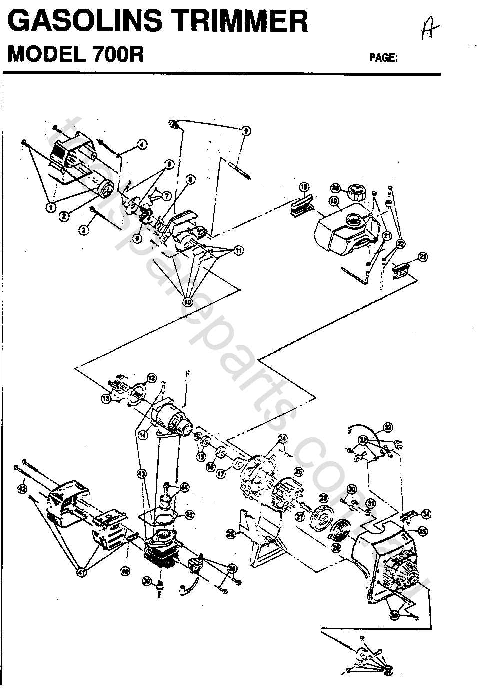
The breakdown of the mechanical structure reveals various essential elements, each playing a critical role in the overall performance. Understanding how these components interact and support the functionality of the device can provide valuable insight into its operation and maintenance. This overview highlights key elements, offering a closer look at their specific roles within the system.
- Engine Assembly: The heart of the system, responsible for driving all mechanical actions through precise combustion processes.
- Fuel System: Ensures proper delivery of the energy source, optimizing power and efficiency during use.
- Ignition Mechanism: Sparks the combustion cycle, triggering the system’s operation with precise timing.
- Transmission and Drive: Transfers the generated power to the active components, enabling movement and operational control.
- Main Engine Assembly Breakdown
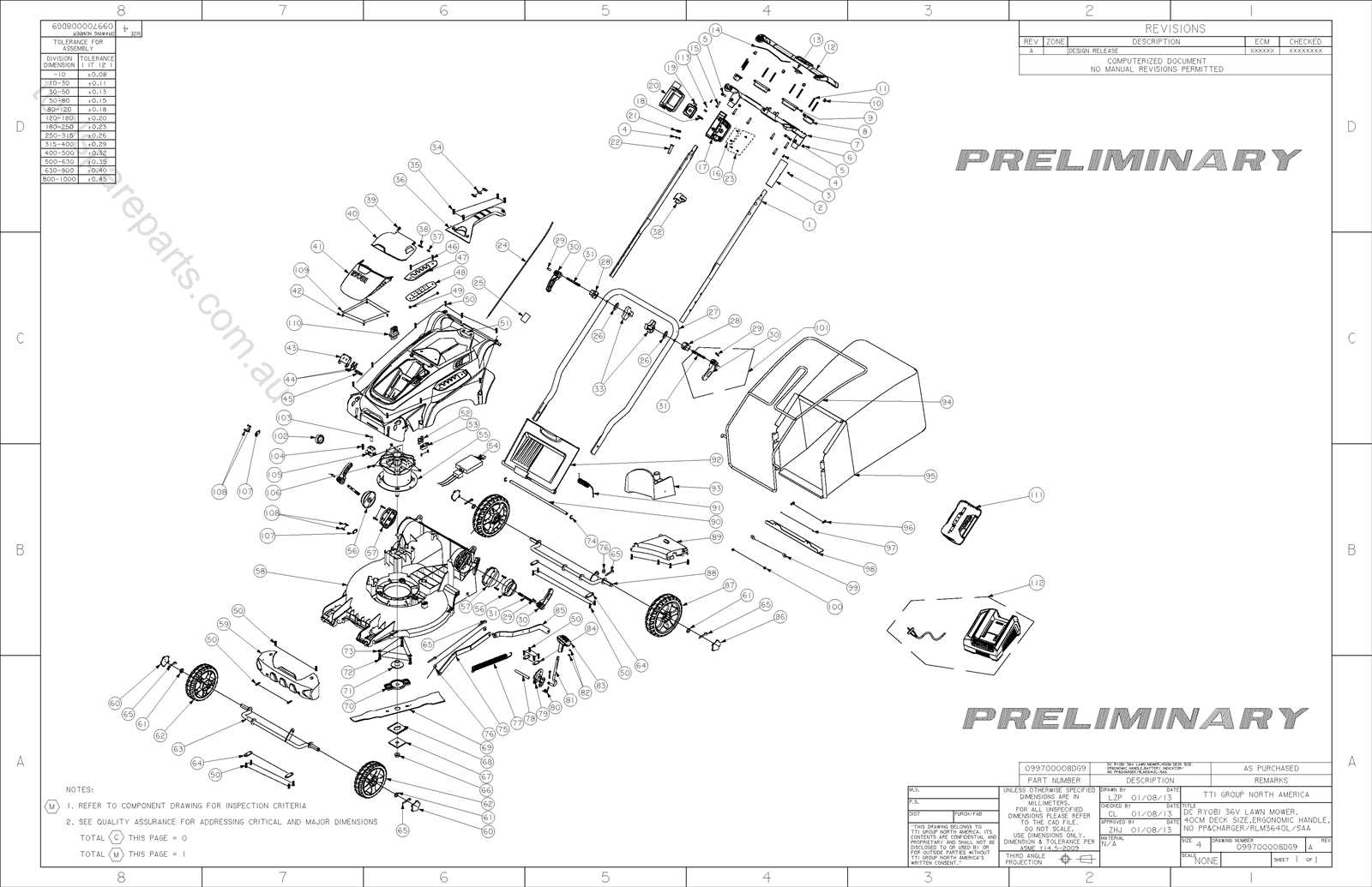
Understanding the composition and key elements of the engine’s core structure is essential for efficient maintenance and troubleshooting. This section focuses on the disassembly and identification of individual components that make up the primary system, highlighting their functions and how they interconnect.
Core Components Overview
- Cylinder Block: The foundational element where various other parts are attached, serving as the housing for internal mechanisms.
- Piston and Connecting Rod: This unit is responsible for the conversion of energy into mechanical movement, transferring power throughout the system.
- Crankshaft: The shaft that converts reciprocating motion into rotational motion, vital for generating movement.
Additional Elements and Their Roles
- Flywheel: Stabilizes engine speed by storing rotational energy, smoothing out the operation.
- Valves and Cam
Fuel System Parts and Functions
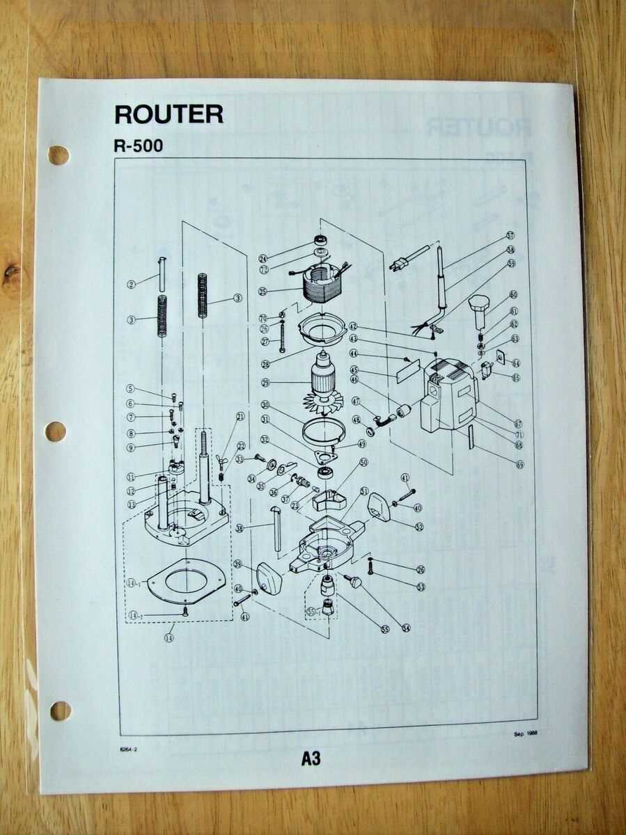
The fuel system is a critical component of any engine, responsible for delivering the right amount of fuel for combustion. Understanding the components involved and their respective roles is essential for ensuring efficient operation. This section will explore key elements and how they work together to keep the engine running smoothly.
Key Components of the Fuel Delivery System
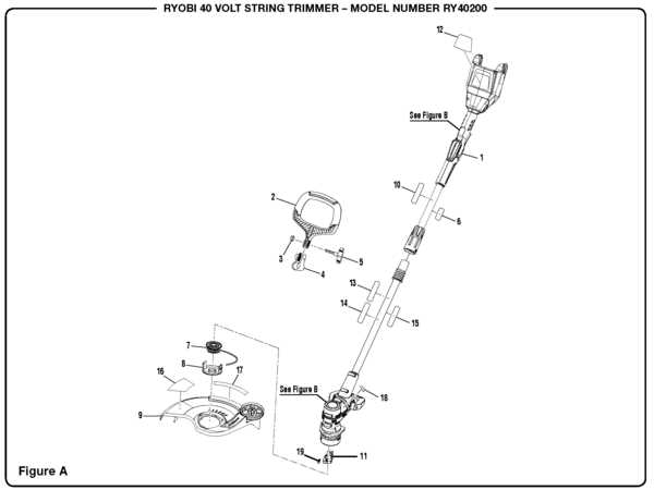
- Fuel Tank: Stores the liquid required for the engine to operate. It’s designed to hold the necessary amount and supply it without leaks.
- Fuel Lines: These conduits transport the liquid from the storage to the engine, ensuring a smooth and uninterrupted flow.
- Fuel Filter: Prevents impurities from reaching the engine by filtering the fluid, thereby ensuring clean combustion.
Additional Functional Elements
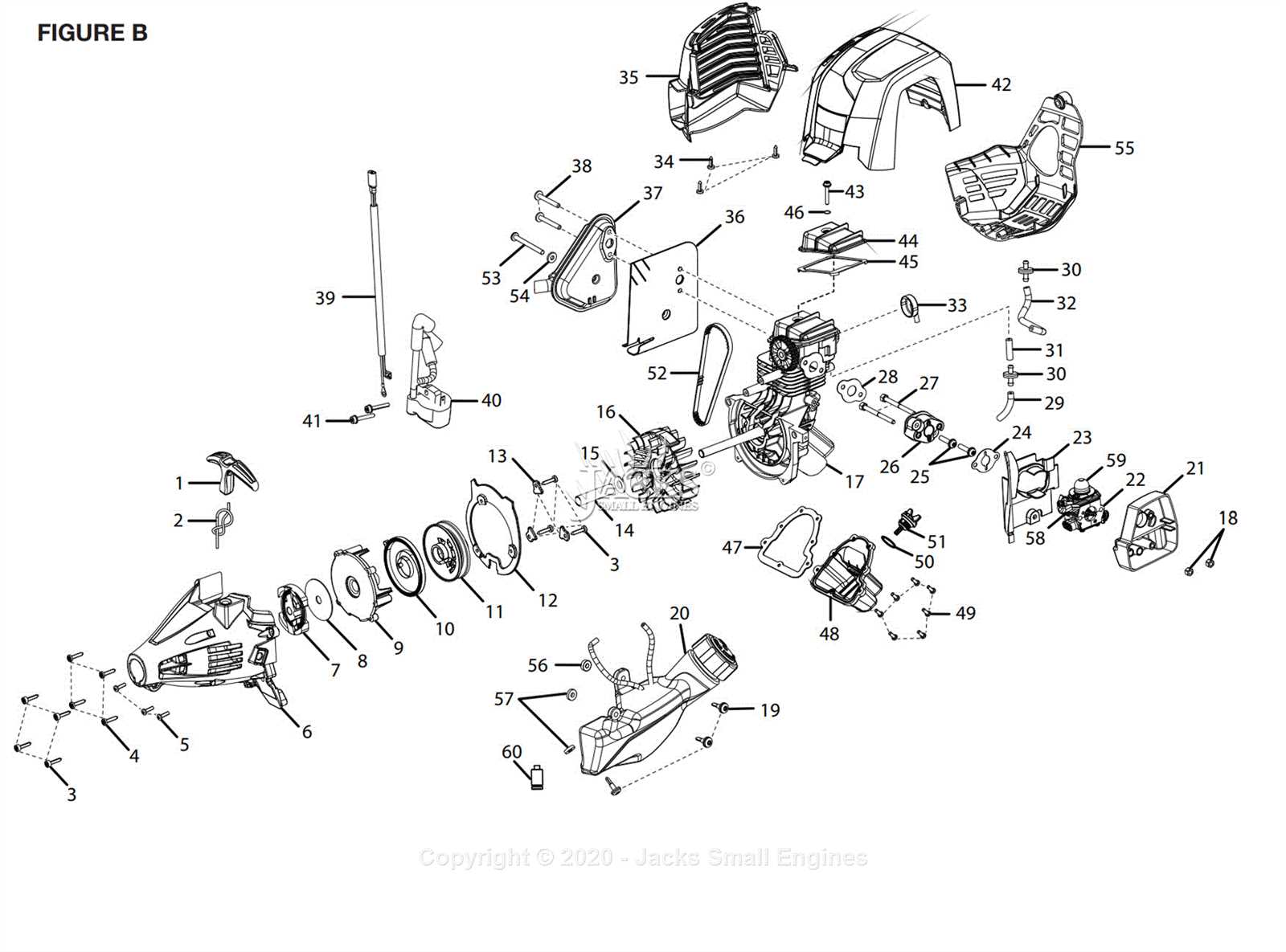
- Ignition Mechanism Components Explained
The ignition system plays a crucial role in starting and maintaining the operation of various equipment. It converts electrical energy into the necessary spark to ignite fuel, ensuring that the engine runs smoothly. This section delves into the various elements that make up this system, highlighting their individual functions and how they work together to create an efficient ignition process.
Key Elements of the Ignition Mechanism
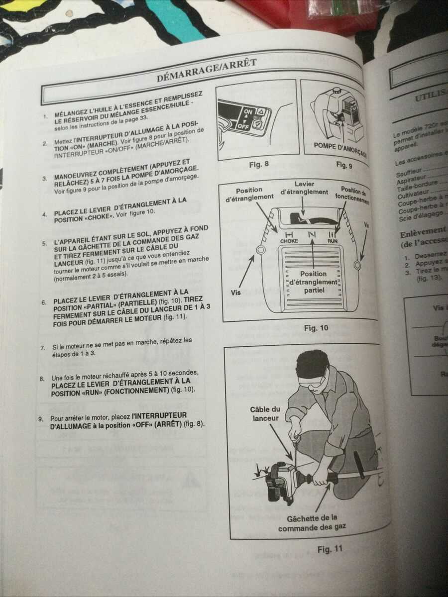
- Spark Plug: The component responsible for producing the spark that ignites the air-fuel mixture in the combustion chamber. This part is crucial for triggering the ignition and keeping the engine running.
- Ignition Coil: This device transforms low voltage into the high voltage required to create a spark. It functions as an energy converter, ensuring the spark plug has enough power to operate efficiently.
- Flywheel: A rotating part that helps generate electricity through magnets attached to its surface. As the flywheel spins, it works in conjunction with the ignition coil to create the necessary electrical current.
Carburetor Structure and Details
The carburetor plays a critical role in ensuring the correct mixture of air and fuel for optimal engine performance. It regulates the intake, balancing both elements to maintain efficient combustion. Understanding its structure helps to grasp how it influences the engine’s overall function.
- Air Intake Passage: This channel allows air to enter, mixing with fuel in the correct proportions to ensure efficient operation.
- Throttle Valve: Controls the amount of air entering the system, which in turn affects engine speed and performance.
- Fuel Jet: Responsible for introducing fuel into the air stream, ensuring precise fuel delivery to the combustion chamber.
- Float Chamber: Maintains a steady level of fuel,
Air Filter Design and Maintenance
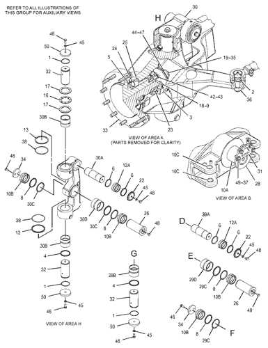
The air filter plays a critical role in ensuring the efficient operation of outdoor power equipment. Its primary function is to trap dirt, dust, and other particles, preventing them from entering the engine and causing damage. Proper design and maintenance of the air filter are essential for prolonging the lifespan of the equipment and optimizing its performance.
Design Considerations: The air filter is typically designed to provide optimal airflow while capturing contaminants. A well-designed filter must strike a balance between filtration efficiency and minimal air restriction. High-quality filters are constructed from durable materials that allow for effective filtration without compromising engine performance.
Maintenance Tips: Regular maintenance is crucial for keeping the air filter in good working condition. Over time, filters can become clogged with debris, reducing their effectiveness. It is recommended to inspect the filter periodically and clean or replace it as needed. In dusty environments, more frequent checks may be required. A clean air filter ensures better engine efficiency and reduces the likelihood of costly repairs.
To maintain optimal performance, always follow the manufacturer’s guidelines for cleaning and replacement. Using the correct filter for your equipment and maintaining it regularly will help prevent engine strain and extend its operational life.
Clutch System Layout
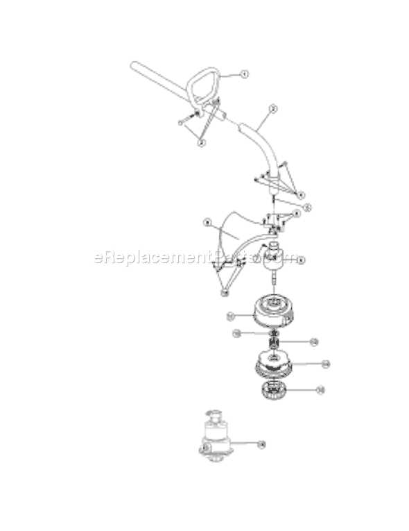
The clutch mechanism plays a crucial role in the smooth operation of the tool, ensuring efficient transfer of power between the engine and the driving elements. Its design facilitates seamless engagement and disengagement, allowing the device to adapt to different operational conditions. A well-designed clutch system helps prevent damage by reducing strain during start-up or sudden load changes.
Components of the Clutch Assembly
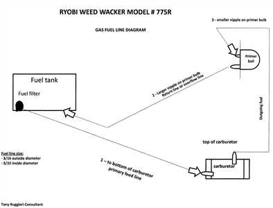
- Friction Plates: These parts engage with each other to transmit torque from the engine to the main drive shaft.
- Springs: Springs are used to maintain the necessary tension for proper clutch operation, ensuring the right balance between engagement and disengagement.
- Clutch Drum: The drum houses the friction plates and facilitates their rotation, allowing the device to transfer power effectively.
Clutch Engagement Process
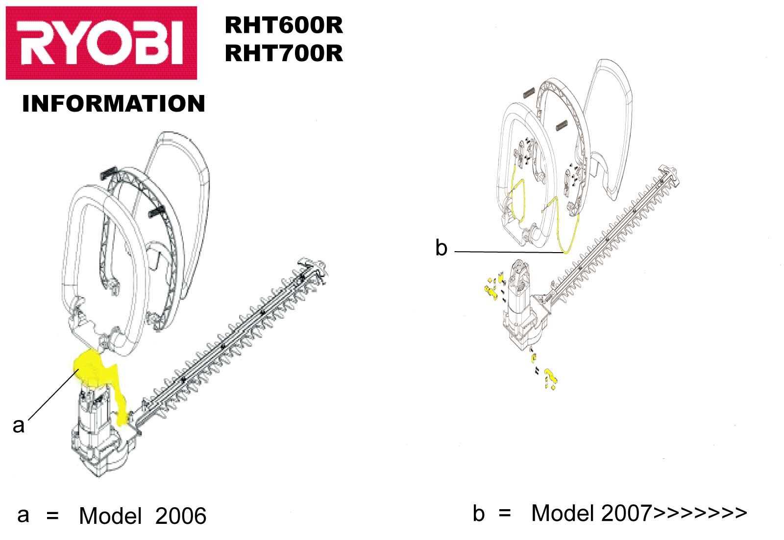
- When the tool is activated, the engine generates power.
- This power is transferred to the clutch mechanism, where friction plates engage, allowing the tool to begin functioning.
- Upon release or when power is no longer needed, the clutch disengages, stopping the transfer of power.
Drive Shaft and Its Components
The drive shaft is a critical element in the transmission system, responsible for transferring power from the engine to the working components. This essential part ensures smooth operation by converting rotational force into motion, enabling the equipment to perform its tasks effectively. Understanding the various components that make up the drive shaft system helps maintain optimal performance and prevent mechanical issues.
The key components of the drive shaft system include:
- Couplings: These connect the drive shaft to the engine and other mechanical parts, ensuring power is transferred efficiently.
- Universal Joints: These allow the drive shaft to pivot and rotate smoothly, compensating for angles and movement between connected parts.
- Bearings: Bearings support the shaft and reduce friction, ensuring smooth rotation and minimizing wear on the components.
- Splines: These are grooves or teeth that fit into corresponding parts, providing a secure connection while allowing for slight movement.
- Seals: Seals protect the drive shaft from dirt, dust, and moisture, preventing contaminants from entering and causing damage.
Each component plays an important role in maintaining the integrity and functionality of the drive shaft system. Proper care and maintenance of these elements ensure long-lasting performance and efficiency in the equipment’s operation.
Handlebar Parts and Adjustment
Proper configuration and adjustment of the handlebar assembly are crucial for ensuring comfort and control during operation. The components that make up this section are designed to provide stability, ease of maneuverability, and personalized fit for the user. Each element plays an important role in enhancing the overall performance of the tool, and fine-tuning them is essential for optimal usage.
Key Elements of the Handlebar Assembly
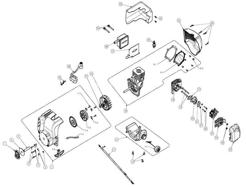
The handlebar system consists of several parts, including grips, levers, and the bar itself. Grips offer a secure hold, reducing fatigue and ensuring control. Levers allow for easy operation of various functions, such as throttle control and safety mechanisms. The bar serves as the central structure, connecting the other elements and providing the foundation for a stable grip.
Adjusting the Handlebar for Comfort
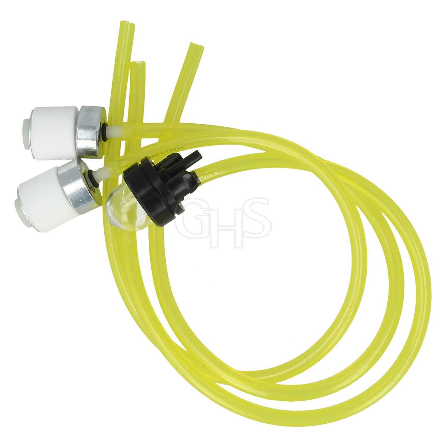
Adjustment of the handlebar is often necessary to accommodate different user preferences or physical dimensions. This can include altering the angle of the bar or adjusting the length of the grips. Proper adjustment helps prevent strain and improves the overall experience by aligning the tool with the user’s posture and grip strength.
Cutting Head Parts Overview
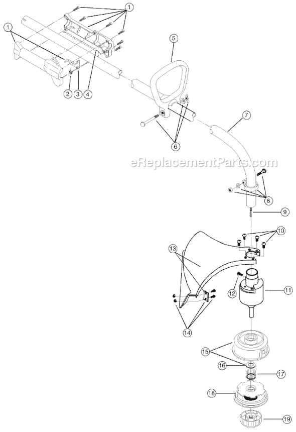
The cutting head is the core component responsible for trimming and shaping vegetation. Its structure consists of several key elements that work together to ensure smooth operation and efficient performance. Understanding the individual components and how they interact can help maintain the tool’s effectiveness and longevity.
Main Components
- Trimmer Spool – Holds the cutting line, allowing it to be fed out as needed during operation.
- Cutting Line – The flexible, durable string used to trim grass and weeds.
- Housing – Encases the spool and protects the internal mechanisms from debris and damage.
- Line Feed Mechanism – A system that controls the release of additional cutting line as it wears down during use.
- Guard – A protective shield that prevents debris from being ejected toward the operator.
Additional Features
- Dual Line Technology – Enables faster cutting with two strands of line instead of one.
- Easy Load System – Simplifies the process of replacing the spool or reloading the line.
- Spool Locking Mechanism – Ensures the spool remains secure during operation.
Starter Assembly Configuration
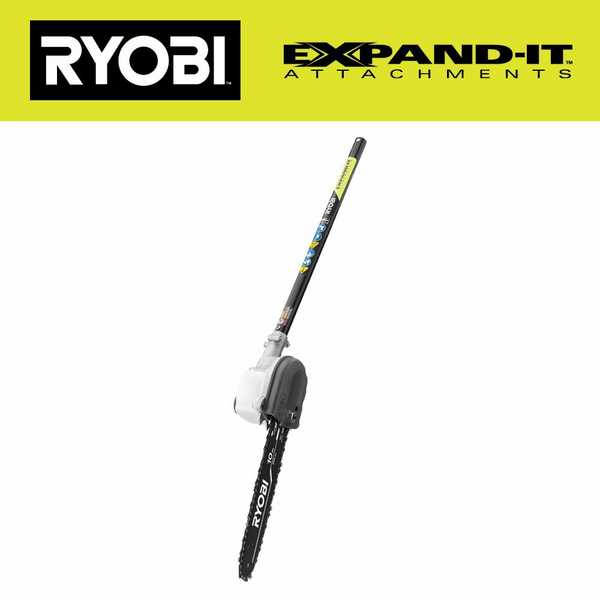
The starter assembly plays a crucial role in the initial operation of the device, ensuring the smooth engagement of the engine and enabling it to run efficiently. Understanding the components involved in this setup is essential for proper maintenance and troubleshooting. Each part is designed to work in harmony to initiate the engine’s movement, transforming mechanical force into the necessary rotational power.
The key components of the starter assembly include:
- Starter motor
- Recoil mechanism
- Pull cord
- Spring components
- Engagement gear
When assembling the starter, it is important to ensure that all parts are properly aligned and securely fastened to prevent malfunction. Regular inspection and maintenance can significantly prolong the lifespan of the assembly.
Exhaust System Parts Breakdown
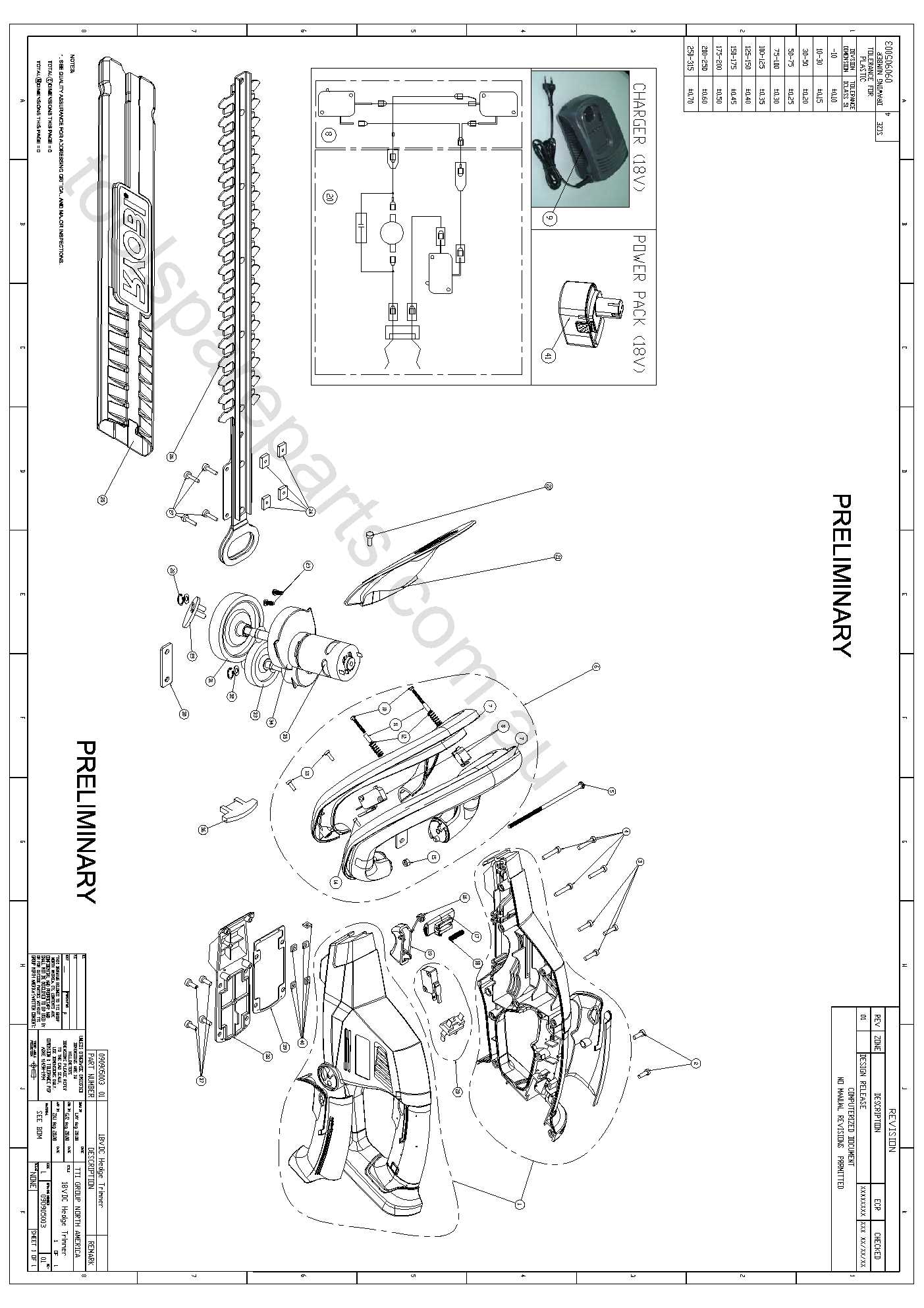
The exhaust assembly plays a crucial role in maintaining optimal engine performance and efficiency. It ensures the safe expulsion of gases produced during the combustion process, preventing buildup and maintaining smooth operation. Understanding the components involved is key to proper maintenance and repair.
The primary elements of the exhaust system include the muffler, which reduces noise, and the exhaust pipe, responsible for directing gases away from the engine. Another important component is the catalytic converter, which helps in reducing harmful emissions. Each part must work in harmony to ensure the system operates efficiently, minimizing environmental impact and enhancing engine longevity.
Additionally, gaskets and mounting brackets are essential for securing the components in place, preventing leaks and ensuring the system is sealed properly. Regular inspections and maintenance of these parts are vital for keeping the equipment running smoothly and preventing unnecessary wear.
Maintenance Tools and Accessories
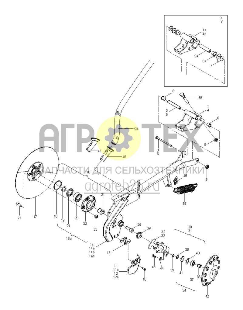
Proper upkeep of your equipment is essential for ensuring its longevity and optimal performance. Having the right tools and supplementary items can make maintenance tasks easier, more efficient, and more precise. Whether it’s for regular upkeep or troubleshooting, the right accessories can significantly enhance the repair process.
Essential tools for maintaining your equipment include screwdrivers, wrenches, and pliers. These basic items allow for easy disassembly and assembly, making it simpler to access internal components. Additionally, lubricants and cleaning agents are critical for maintaining smooth operation and preventing wear and tear on moving parts.
For specialized tasks, precision tools like torque wrenches and multimeters are highly recommended. These tools ensure that all components are correctly calibrated and functioning as intended, contributing to a more efficient and safe operation.
Moreover, various replacement accessories such as filters, gaskets, and seals are vital for the longevity of your equipment. Having a stock of these items readily available helps to prevent downtime and ensures that repairs can be done swiftly without delays.