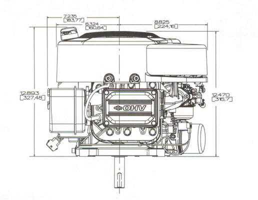
The layout of mechanical systems often requires a detailed understanding of how various components work together. When working with small power solutions, it’s essential to have a clear view of how each element fits within the overall structure. This allows for efficient troubleshooting and maintenance, ensuring the machinery continues to function smoothly.
Mechanical systems like these are known for their durability and reliability, but proper care is crucial. By familiarizing yourself with the individual connections and mechanisms, you’ll be better equipped to handle repairs or replacements. This knowledge can extend the lifespan of your equipment and improve performance.
In the following sections, you’ll explore a well-organized breakdown of the system’s structure, focusing on the most critical connections and assemblies. With this comprehensive guide, even those new to the setup can quickly grasp the essential components and their functions, facilitating smoother operation and care.
Overview of the 17 HP Engine Structure
The 17 HP power unit is designed with a robust configuration that optimizes performance and longevity. Its overall architecture is intended to deliver consistent power output, ensuring smooth operation across various applications. By incorporating a system of interconnected components, this power source achieves a balance between efficiency and reliability.
The core structure is built to handle significant mechanical stress, with a focus on durability. Its layout includes key elements that work together to facilitate combustion, power transfer, and heat dissipation, ensuring that the system remains functional under demanding conditions.
Attention to detail in the internal configuration allows for minimal energy loss, enhancing fuel efficiency and maintaining steady operation. The integration of precision-machined parts ensures that the system functions cohesively, maximizing both performance and reliability.
Key Components of the Briggs and Stratton Motor
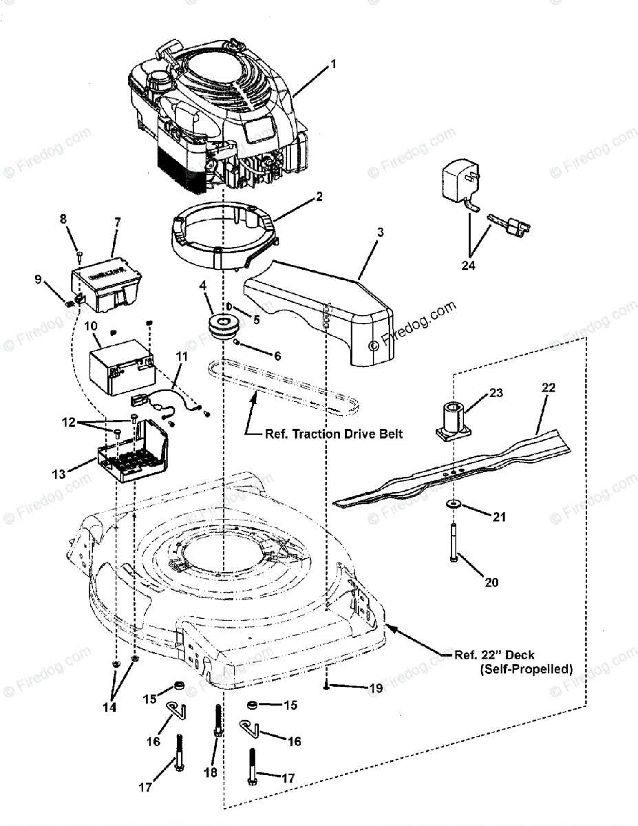
The internal structure of this type of motor relies on various crucial mechanisms working together in harmony. Each of these elements plays a significant role in ensuring smooth functionality, efficient fuel consumption, and optimal power output. Understanding these fundamental components is essential for maintenance and repair, as they form the backbone of the motor’s operation.
The core of the motor consists of a combustion chamber where fuel mixes with air to produce energy. Surrounding this area, you’ll find moving parts like pistons, rods, and valves that handle the mechanical side of energy conversion. These elements must be perfectly timed and synchronized to maintain balance and performance.
Fuel delivery and ignition systems work together to ensure that the motor receives the right amount of fuel and air at the correct time. The precision of these systems is key to achieving reliable power. Cooling and lubrication systems help manage heat and reduce wear, keeping all the moving parts in good condition over time.
Finally, external features such as the exhaust and control mechanisms play vital roles in managing emissions and adjusting the motor’s output. Each of these components is integral to the overall functionality and longevity
Internal Mechanisms and Their Functions
The inner workings of this mechanical system are key to ensuring efficient performance. Each component is meticulously designed to contribute to the overall operation, working together to convert energy into motion. Understanding how these elements interact is crucial for maintaining optimal functionality and resolving potential issues.
Power Generation
The heart of the system is responsible for producing the necessary force to drive the entire unit. Various moving parts create the required power by harnessing combustion, delivering this energy to other critical mechanisms. Each element plays a role in controlling and guiding this process.
Control and Regulation
Several smaller mechanisms manage the flow of energy, ensuring that everything operates smoothly and at the correct pace. These components act as regulators, preventing overloads and maintaining balance within the system. By coordinating the power distribution, they guarantee stable and continuous operation.
Understanding the Fuel System Layout
The fuel system is an essential component that ensures the smooth operation of the machine by providing the necessary flow of energy. This section covers the key elements responsible for delivering fuel, explaining how these components work together to maintain performance. Recognizing the structure and flow is vital for troubleshooting and maintaining the overall efficiency of the equipment.
Main Components Overview
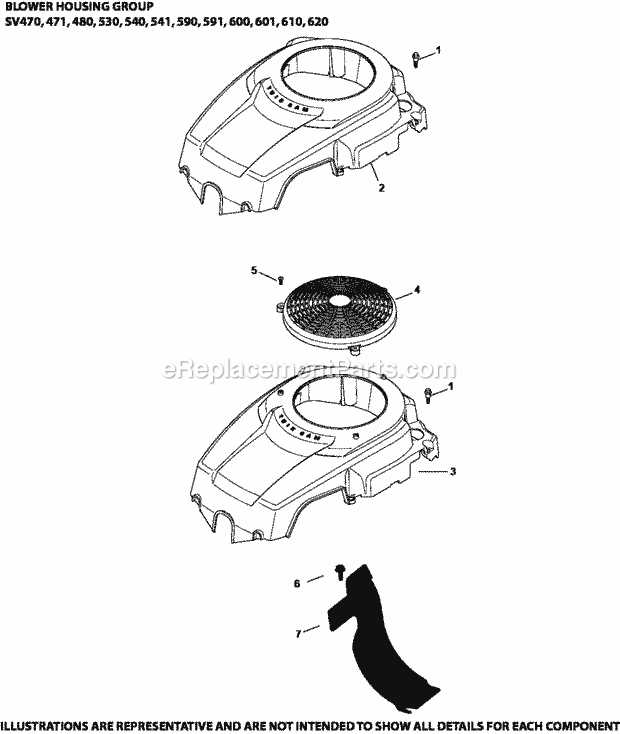
The primary elements of the fuel system include a storage unit, delivery lines, and regulation devices. Each plays a critical role in transferring the liquid from the tank to the combustion area. Understanding how these parts interact allows for a better grasp of maintenance requirements and potential areas where issues may arise.
Flow and Regulation Mechanism
Fuel must travel smoothly from the storage point to the area where it is utilized. Along the way, valves and filters regulate its movement, ensuring a clean and consistent flow. Identifying how the system manages both flow rate and quality helps to prevent operational problems and extend the life of the machine.
Electrical Wiring and Power Connections
The electrical wiring setup ensures that the power flows correctly to all the necessary components. Properly managing the electrical connections is crucial for maintaining efficiency and preventing malfunctions.
Below are key considerations for connecting the power systems:
- Ensure secure connections to avoid loose wires that can cause power loss or short circuits.
- Verify the correct voltage and current ratings for all wiring to prevent overheating or damage.
- Utilize insulated cables for improved safety and durability in harsh environments.
- Check all grounding connections to maintain stable electrical performance.
Additionally, regular inspection of the wiring layout is recommended to identify any potential wear or damage before it leads to failure.
Cooling System and Airflow Pathways
The effectiveness of any motor relies heavily on its ability to manage heat. A well-designed cooling mechanism plays a crucial role in maintaining optimal operating temperatures, ensuring longevity and efficiency. This section delves into the essential components and airflow pathways that facilitate effective thermal regulation in small power units.
At the heart of the cooling system is the circulation of air and fluids, which dissipate heat generated during operation. Key elements contributing to this process include:
- Cooling Fins: Located on the exterior of the housing, these structures enhance heat dissipation by increasing surface area.
- Fan Assembly: This component actively moves air across the cooling fins, significantly improving airflow and cooling efficiency.
- Intake Ducts: These pathways guide fresh air into the unit, ensuring that the cooling process remains efficient.
- Exhaust Ports: Designed to expel heated air, these outlets are critical for preventing heat buildup.
Understanding the airflow pathways is vital for optimizing the cooling system. The arrangement of these components ensures that cool air is drawn in and heated air is effectively expelled, creating a continuous flow. Proper airflow not only enhances cooling but also contributes to the overall performance of the equipment.
Regular maintenance of the cooling system is essential for preventing overheating and ensuring longevity. This includes cleaning air filters, checking fan operation, and inspecting duct integrity. Adhering to these practices will help maintain efficient airflow and cooling performance.
Lubrication System Breakdown
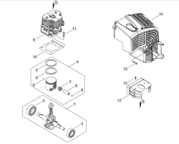
The lubrication mechanism within a small power unit plays a crucial role in maintaining its performance and longevity. This system ensures that moving components receive adequate oil, reducing friction and preventing wear. Understanding the intricacies of this mechanism can help in troubleshooting issues and performing effective maintenance.
Key Components of the Lubrication Mechanism
Central to the lubrication system are several essential components. The oil sump collects the lubricant, while the oil pump circulates it to critical areas. Additionally, filters play a significant role in removing impurities, ensuring the fluid remains clean and effective. Each element is designed to work harmoniously, contributing to the overall efficiency of the machine.
Importance of Regular Maintenance
Routine maintenance of the lubrication system cannot be overstated. Neglecting this aspect can lead to serious consequences, such as overheating or catastrophic failure. Regular oil changes, along with inspections of the pump and filters, help to ensure optimal performance. Adhering to the manufacturer’s guidelines regarding oil type and change intervals will further enhance reliability and efficiency.
Examining the Ignition Module Assembly
The ignition module assembly is a crucial component responsible for generating the spark needed to ignite the fuel-air mixture in the combustion chamber. Its proper functioning is essential for optimal performance and efficiency of the machine. Understanding its structure and role can greatly assist in troubleshooting and maintenance efforts.
Components of the Ignition Module
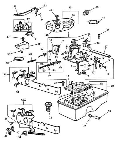
This assembly typically comprises several key elements, including the coil, spark plug connector, and various wiring components. The coil transforms low voltage into the high voltage required to create a spark. The spark plug connector ensures a secure link between the module and the spark plug, facilitating the ignition process. Each component plays a vital role in ensuring the assembly operates smoothly and effectively.
Troubleshooting Common Issues
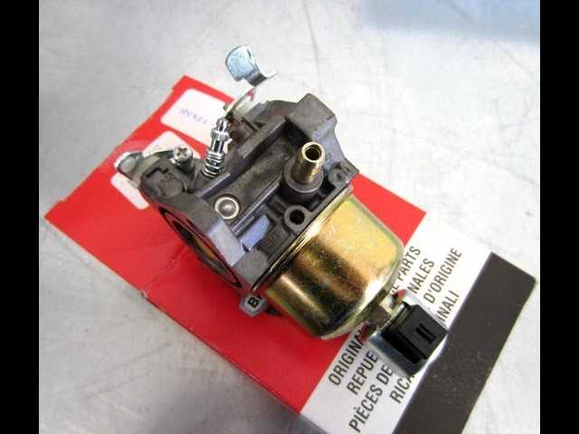
When problems arise, symptoms may include difficulty starting, irregular running, or stalling. To diagnose issues, inspect the module for signs of wear, loose connections, or damage. Testing the output voltage can also help determine if the module is functioning correctly. Regular maintenance and careful attention to the ignition module can prevent many common issues, ensuring reliable performance.
Carburetor Components and Adjustments
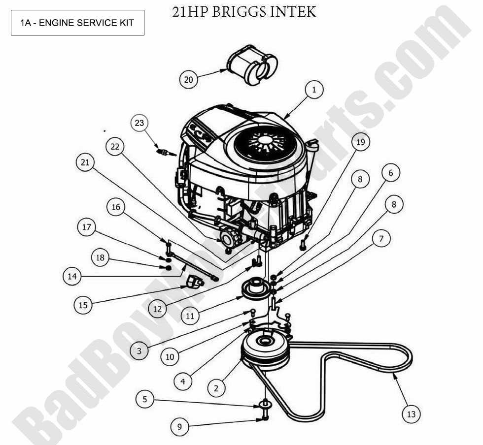
The carburetor is a crucial element in the functioning of small motors, responsible for mixing air and fuel in the correct proportions to facilitate combustion. Understanding its structure and functionality is essential for optimal performance and efficiency. This section delves into the various components of the carburetor, detailing their roles and the adjustments that can be made to enhance operation.
Key components of the carburetor include the float chamber, needle valve, and jets. The float chamber maintains a consistent fuel level, while the needle valve regulates the flow of fuel into the chamber. Jets play a vital role in atomizing the fuel, ensuring it mixes well with air before entering the combustion chamber. Each component must function harmoniously to achieve the desired mixture for efficient operation.
Adjustment of the carburetor is necessary to ensure optimal performance, particularly in varying environmental conditions. Common adjustments include altering the idle speed and the air-fuel mixture. The idle speed screw controls how quickly the motor runs when at rest, while the mixture screw fine-tunes the ratio of air to fuel, impacting acceleration and power delivery. Regularly checking and adjusting these settings can lead to smoother operation and improved fuel efficiency.
It is important to note that improper adjustments can lead to issues such as stalling, rough running, or excessive fuel consumption. Therefore, familiarity with the components and their respective adjustments can significantly enhance the longevity and functionality of the motor.
Crankshaft and Piston Configuration
The relationship between the crankshaft and piston is fundamental in the operation of small power units. This connection transforms linear motion into rotational force, facilitating the machine’s functionality. Understanding this interplay is crucial for maintenance and repair, ensuring optimal performance and longevity.
Components Overview
The primary components involved in this configuration include the crankshaft, which serves as the main rotating part, and the piston that moves within the cylinder. Together, these elements work to convert combustion energy into mechanical motion.
Functionality of Crankshaft and Piston
The crankshaft rotates as the piston moves up and down, driven by combustion pressure. This movement is essential for creating the necessary torque to power various attachments or machinery. An efficient setup ensures that the power unit operates smoothly, minimizing wear and tear.
| Component | Function |
|---|---|
| Crankshaft | Converts linear motion of the piston into rotational energy. |
| Piston | Moves within the cylinder, driven by combustion forces. |
| Connecting Rod | Links the piston to the crankshaft, facilitating motion transfer. |
Gasket Placement and Sealing Techniques
Proper positioning and sealing of gaskets play a crucial role in ensuring optimal performance and longevity of mechanical assemblies. The effectiveness of a seal depends not only on the gasket material but also on its correct installation. Understanding how to effectively place and secure these components can prevent leaks and maintain pressure in various applications.
Importance of Accurate Gasket Installation
Accurate placement of gaskets is vital for the reliability of any mechanical system. Misalignment or improper fitting can lead to fluid leaks, which can compromise performance and cause damage over time. Ensuring that the surface is clean and free from debris before installation enhances the integrity of the seal.
Sealing Techniques
Several methods can be employed to enhance gasket sealing capabilities. Here are some commonly used techniques:
| Technique | Description |
|---|---|
| Surface Preparation | Cleaning the surfaces to remove any contaminants that may affect adhesion. |
| Even Pressure Distribution | Applying uniform torque across all fasteners to ensure the gasket is compressed evenly. |
| Use of Sealants | Incorporating adhesive or sealant compounds can provide additional sealing strength. |
| Temperature Considerations | Taking into account the operating temperature to select the appropriate gasket material. |
Valve System Operation and Maintenance
The valve system plays a crucial role in regulating airflow and ensuring efficient combustion within the power unit. Understanding its operation and maintenance is vital for optimal performance and longevity. Properly functioning valves contribute to the overall efficiency and reliability of the machinery, preventing issues such as misfires or power loss.
Operation of the Valve Mechanism
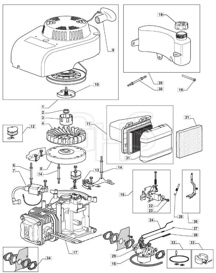
The valve mechanism consists of various components that work in unison to control the intake and exhaust of gases. During operation, the intake valve opens to allow a mixture of air and fuel into the combustion chamber, while the exhaust valve opens to release the spent gases after combustion. This sequence is carefully timed and controlled by the camshaft, ensuring that each valve operates at the right moment for maximum efficiency.
Maintenance Tips for Optimal Performance
Regular maintenance of the valve system is essential to prevent wear and ensure smooth operation. Here are some key maintenance tips:
| Maintenance Task | Frequency | Description |
|---|---|---|
| Check Valve Clearance | Every 100 hours | Ensure proper clearance to allow for efficient valve operation and prevent excessive wear. |
| Inspect Valve Components | Every season | Examine the condition of the valves, springs, and retainers for signs of wear or damage. |
| Replace Damaged Parts | As needed | Replace any worn or damaged components to maintain optimal function and performance. |
| Clean Valve Seats | Every 200 hours | Remove carbon buildup from valve seats to ensure a tight seal and prevent leakage. |